


16
MOLDING INSTALLATION
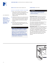
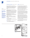
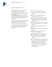
The decorative white molding strips for the
side and top of the unit can be snapped into
place. The top molding strip used on
Integrated tall units, must be installed before
the side molding can be attached. The top
molding strip is held in place by double-sided
velcro fasteners. Refer to illustration 8 below
for positioning of the top molding.
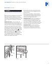
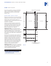
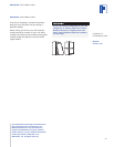
Illustration 9 shows side molding installation
for tall units. Installation of the side molding
for base units is the same. For installations
where units are side by side, refer to Dual
Installations on page 21.
NOTE:
The molding strips may be painted
to match the surrounding cabinetry, if you
choose. Follow these easy steps:
Rough up the surface to be painted with
fine grit sandpaper.
Wipe with alcohol to ensure that the surface
is clean and dry.
Use an appliance or industrial grade, oil
base, high gloss enamel paint.
INTEGRATED INSTALLATION INSTRUCTIONS
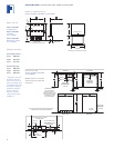
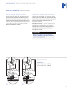
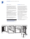
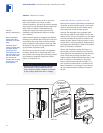
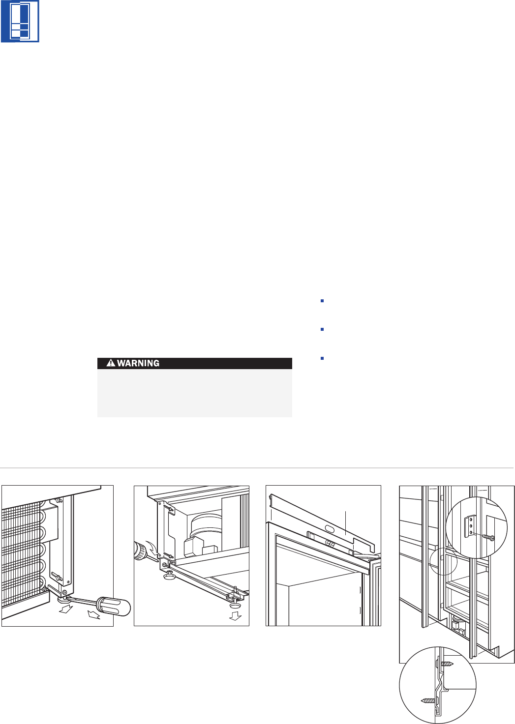
LEVEL THE UNIT
Level the Integrated unit by turning the front
leveling legs clockwise to raise the unit, or
counterclockwise to lower it. To assist you in
adjusting the front leveling legs up or down,
use a standard screwdriver blade and place it
in the front leveling leg as shown in illustration
6 below.
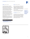
The rear leveling legs are adjusted from the
front of the base by turning the Phillips head
screw. Refer to illustration 7.
IMPORTANT NOTE:
The rear leveling legs will
only move 2 mm for every 18 revolutions on
the Phillips head screw. Do not over torque.
Use the lowest torque setting on any power
screwdriver. Do not turn the rear leveling legs
by hand. Damage will occur if you turn these
legs.
Once the unit is leveled, secure the unit in
place by using the side mounting clips and
#8 x 12,7 mm screws provided.
To reduce the possibility of the unit
tipping forward, the front leveling legs
must be in contact with the floor.
Top Molding
Illus. 6 Illus. 7 Illus. 8
Illus. 9