


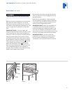
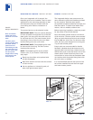
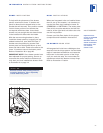
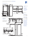
DRAWER PANEL INSTALLATION
Remove the mounting hardware provided and
set aside. As with the door panel, you should
work on the back side of each drawer panel
and protect the fronts of these panels.
Position the top edge of the template flush
with the top edge of each drawer. For the top
drawer, there is only one location for the lower
mounting bracket to be placed. However, the
bottom drawer allows a second option, invert-
ing the lower mounting bracket, depending on
the height and thickness or detail of the panel.
Refer to illustration 15 below.
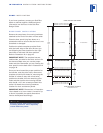
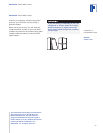
Secure the template in place with tape or a
small clamp and mark positions for the pilot
holes. Remove the template and drill the pilot
holes. Place the mounting brackets in the
proper location with the tabbed bracket on top
and ’L’ bracket on the bottom of the panel.
Fasten brackets securely with the #8 x 12,7
mm screws provided. Refer to illustration 16
below. Illustration 13 on page 17 also shows
the mounting hardware location for drawer
panels.
20
INTEGRATED INSTALLATION INSTRUCTIONS
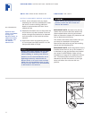
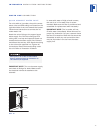
PANEL
REQUIREMENTS
Door and drawer
panels must be a
minimum of 16 mm
thick.
The door panel
cannot exceed 18 kg
and each drawer
panel must not
exceed 5 kg for 686
mm wide units. For
914 mm wide units,
the door panel
weight limit is 24 kg
and 7 kg for each
drawer panel.
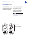
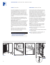
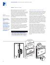
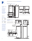
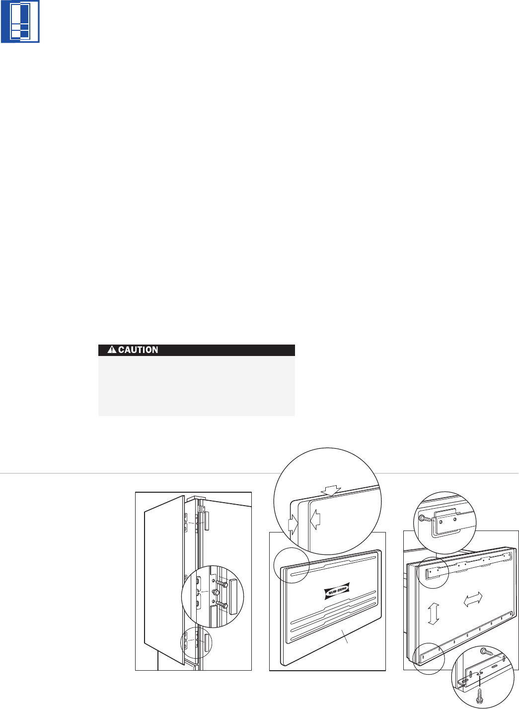
PANEL INSTALLATION
Before attaching the door panel to the door,
place two screws in the center of each
mounting position, just enough that the slotted
holes on the hinge side door panel bracket will
slide under the heads. These positioning
screws will support the door panel during
installation and adjustment. Refer to illustra-
tion 14 below.
Install the door panel by engaging the tabbed
bracket to the handle side of the door first and
then sliding the hinge side mounting bracket
onto the positioning screws on the hinge side
of the door. The panel can be adjusted 6 mm
up and down and side to side.
Once the door panel is in place and adjusted
correctly, attach the six remaining #10 x 12,7
mm screws to the hinge side mounting bracket
and install the magnetic decorative caps as
shown in illustration 14.
As the reveal between cabinets and the
unit decreases, the potential exists for
severe finger pinching if fingers are placed
in the opening when the door is closing.
Back Of
Drawer Panel
Gap On Side
Edges Will Vary
According To
Design
Top Of Template
Flush With Top Of
Drawer Panel
Illus. 14 Illus. 15 Illus. 16