


1
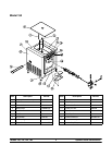
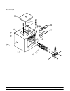
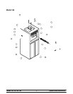
Models 150, 152, 162, 168 To the Installer
031030
Section 1 To the Installer
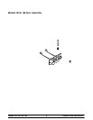
Air Cooled Units
The models 150 and 152 require a minimum of 6” (152
mm) of clearance around both sides. Install the skirt
provided on the right side of the unit and place the back
of the unit against a wall to prevent recirculation of
warm air. The model 162 requires 6” (152 mm) on all
sides and the skirt installed on the rear of the unit. The
model 168 requires 3” (76 mm) on all sides and the
skirt installed on the r ear of the unit. Minimum air
clearances must be met to assure adequate air flow for
optimum performance.
These machines are designed for indoor use only.
DO NOT install the machines in an area where
a water jet could be used. Failure to follow this
instruction may result in serious electrical shock.
Electrical Hook-Up Installation For
60 Cycle, 1 Phase, Supplied With Cord and Plug
This equipment is supplied with a 3- wire cord and
grounding type plug for connection to a single phase,
60 cycle, branch circuit supply. This unit must be
plugged into a properly grounded receptacle. The cord
and plug provided for 115/ 60/1, is 20 amp; therefore
the wall outlet must also be 20 amp. Check the data
label, located on the side panel, for electrical
specifications.
Permanent wiring may be employed if required by local
codes. Instructions for conversion to permanent wiring
are as follows:
1. Be sure the freezer is electrically disconnected.
2. Remove the appropriate panel and locate the
small electrical box at the base of the freezer .
3. Remove the factory-installed cord and strain
relief bushing.
4. Route incoming permanent wiring through 7/8”
(22 mm) hole in base pan.
5. Connect two power supply leads. Attach ground
(earth) wire to the grounding lug inside the
electrical box.
6. Be sure the unit is properly grounded before
applying power.
FOLLOW YOUR LOCAL ELECTRICAL CODES!
Electrical Connections For
Models Without Cord and Plug Supplied
Each freezer requires one power supply for each data
label. Check the data label(s) on the freezer for fuse,
circuit ampacity and electrical specifications. Refer to
the wiring diagram provided inside of the control box,
for proper power c onnections.
In the United States, this equipment is intended to be
installed in accordance with the National Electrical
Code (NEC), ANSI/NFPA 70--1987. The purpose of
the NEC code is the practical safeguarding of persons
and property from hazards arising from the use of
electricity. This code contains provisions considered
necessary for safety. Compliance therewith and
proper maintenance will result in an installation
essentially free from hazard! In all other areas of the
world, equipment should be installed in accordance
with the existing local codes. Please contact your local
authorities.
Stationary appliances which are not equipped with a
power cord and a plug or other device to disconnect
the appliance from the power source must have an
all--pole disconnecting device with a contact gap of at
least 3 mm installed in the external installation.
CAUTION: This equipment must be
properly grounded! Failure to do so can result in
severe personal injury from electrical shock!
Beater rotation must be clockwise as viewed looking
into the freezing cylinder.
Note: The following procedures should be performed
by an authorized service technician.
To correct rotation on a three-phase unit, interchange
any two incoming power supply lines at freezer main
terminal block only. To correct rotation on a
single-phase unit, change the leads inside the beater
motor. (Follow diagram pr inted on motor.)
Electrical connections are made directly to the
terminal block provided in the splice box, mounted on
the base pan on each side of the model 168, and
located in the splice boxes mounted mid-level on the
frame channel on the sides of the model 162.