


7
Model 390 Operating Procedures
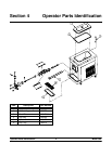
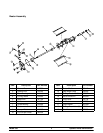
Section 6 Operating Procedures
Following are step-by-step operating procedures for
the model 390 slush freezer. This unit has a 20 quart
(18.9 liter) mix hopper and the freezing cylinder holds
7 quarts (6.6 liters) of slush product.
We begin our instructions at the point where we enter
the store in the morning and finds the parts
disassembled and laid out to air dry from the previous
night’s brush cleaning.
These opening procedures will show you how to
assemble these parts into the freezer, sanitize them
and prime the freezer with the slush base you have
selected in preparation to serve your first portion.
If you are disassembling the machine for the first time
or need information to get to this starting point in our
instructions, turn to ”Disassembly” on page 10, and
start there.
Assembly
BE SURE THE CONTROL SWITCH IS IN
THE “OFF” POSITION. Failure to do so may cause
injury from electrocution or hazardous moving parts.
Note: When lubricating parts, use an approved food
grade lubricant (example: Taylor Lube).
Step 1
Install beater drive shaft. Slide the o-ring into the first
groove on the drive s haft. Lubricate the groove, o-ring,
and shaft portion that comes in contact with the
bearing on the beater drive shaft. DO NOT lubricate
the hex end of the d rive shaft. Slide the seal over the
shaft and groove until it snaps into place. Fill the inside
portion of the seal with 1/4” more lubricant and evenly
lubricate the flat side of the seal that fits onto the rear
shell bearing.
Install the drive shaft into the f reezing cylinder , hex end
first, and into the rear shell bearing until the seal fits
securely over the rear shell bearing. Be certain the
drive shaft fits into the drive coupling without binding.
Step 2
Before installing the beater assembly, check the
scraper blades for any nicks or signs of wear. If any
nicks are present or if the blade is worn, replace both
blades. If blades are in good condition, install the
scraper blade clip over the scraper blade. Place the
rear scraper blade over the rear holding pin (knife edge
to the outside). Holding the blade on the beater, turn
it over and install the front blade the same way.
Holding the blades in pos ition, insert the beater
assembly into the freezing cylinder and slide into
position over the drive shaft. Turn the beater slightly t o
be certain that the beater is properly seated. When in
position, the beater will not protrude beyond the front
of the freezing cylinder.
Step 3
Install the baffle assembly. Lubricate the o-ring, and
install it on the front end of the baffle assembly. Install
the guide bearing o n the rear end of the baffle
assembly.
Install the bearing end of the baf fle assembly into the
pilot hole in the drive shaft.
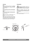
Step 4
Assemble the freezer door with the “Ice Buster” (door
spout clearing device). To assemble the door with the
ice buster, install the o-rings on the draw valve and
lubricate. (See illustrations on page 10.)
Insert the draw valve into the door, leaving
approximately 1/2” of the valve sticking out the top of
the door.
Rotate the draw valve so the flats on the top of thedraw
valve are perpendicular to the door f ace ( see
illustration).
Insert the ice buster through the door spout and into
the slot located just above the lower o-ring.
With the ice buster in place, rotate the draw valve to
allow installation of the draw handle. This will lock the
ice buster in place. Install the draw handle pin, and
close the draw valve by moving the handle to the left.
Place the large rubber gasket into the groove on the
back side of the freezer door.
Slide the white plastic front bearing onto the bearing
hub making c ertain that the flanged end of the bear ing
is resting against the freezer door. Do not lubricate the
door gasket or front bearing.