


18
Operating Procedures
Model 632
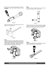
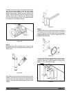
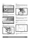
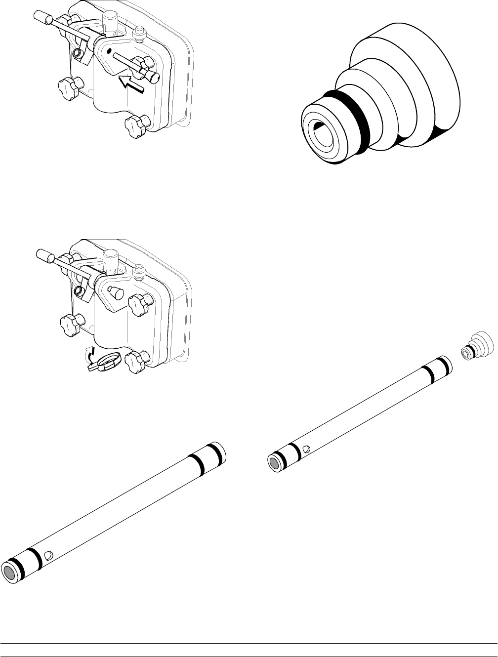
Slide the fork over the bar in the slot of the draw valve.
Secure with pivot pin.
Figure 1 4
Note: These units feature adjustable draw handles to
provide the best portion control. The draw handles can
be adjusted for different flow rates. See page 14 for
more information on adjusting these handles.
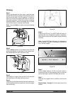
Step 7
Snap the design cap over the end of the door spout.
Figure 1 5
Step 8
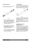
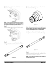
Slide two o--r ings on one end of the air tube. Slide two
o--rings on the other end of the air tube.
Figure 1 6
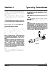
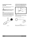
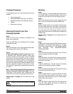
Slide the small o--r ing into the groove of the air orifice.
Do not lubricate the o--ring.
Figure 1 7
Note: Make sure the hole in the air orifice is clean and
is not clogged. If the hole in the air orifice s hould
become clogged, use soap and hot water to clear the
hole. Do not enlarge the hole in the air orifice.
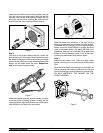
Install the air orifice into the hole in the top of the air
tube (in the end without the small hole on the side).
Figure 1 8
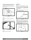
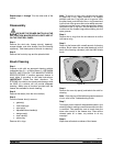
Step 9
Lay the air tube (with the air orifice installed) in the
bottom of the mix hopper for sanitizing.
Note: The air tube for the shake side does not require
o--rings or an air orifice.