


12
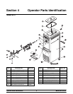
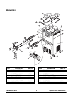
Models 8751/8754Important: To the Operator
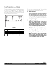
WASH Key
When the WASH key is pressed, the light c omes on.
This indicates beater motor operation. The STANDBY
or AUTO modes must be cancelled first to activate the
W ASH m ode.
AUTO Key
When the AUTO key is pressed, the light comes on.
This indicates that the main refrigeration system has
been activated. In the AUTO mode, the W ASH or
STANDBY functions are automatically cancelled. The
MIX REF function is automatically locked in to
maintain the mix in the mix hopper.
Note: An indicating light and an audible tone will
sound whenever a mode of operation has been
pressed. To cancel any f unction, pr ess the key again.
The light and mode of operation will shut off.
Pump Key
When the PUMP key is pressed, the light comes on,
indicating the a ir/mix pump will operate as required.
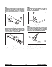
Reset Button
The reset button is located in the s ervice panel on the
front of the machine. The reset protects the beater
motor from a n overload condition. If an overload
occurs, the reset mechanism will trip. To properly reset
the freezer, press the AUTO key to cancel the cycle.
T urn the power switch to the O FF position. Press the
reset button firmly.
Do not use metal objects to press the reset
button. Failure to follow this instruction may
result in electrocution.
T urn the power switch to the ON position. Press the
W ASH key and observe the freezer’s performance.
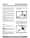
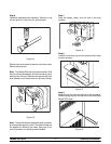
Open the side access panel. Make sure the beater
motor is turning the drive shaft in a clockwise direction
(from the operator end) without binding.
If the beater motor is turning properly,press the WASH
keytocancelthecycle. PresstheAUTO key toresume
normal operation. If the freezer shuts down again,
contact a service technician. (For the Model 8754
press the AUTO keyon both sidesof theunit to resume
normal operation.)
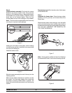
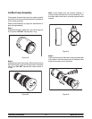
Air/Mix Pump Reset Mechanism
The reset button for the pump is located in the service
panel. The reset p rotects the pump from an overload
condition. Should an overload occur, the reset
mechanism will trip. To reset the pump, press the reset
button firmly.
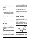
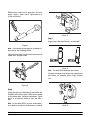
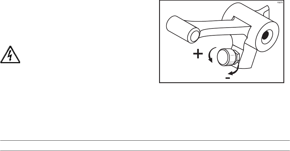
Adjustable Draw Handle
These units feature a n adjustable draw handle to
provide the best portion control. The draw handle
should be adjusted to provide a flow rate of 5 to 7-1/2
oz. (148 to 222 ml) of product per 10 seconds. To
INCREASE the flow rate, turn the screw
COUNTERCLOCKWISE. Turn the screw
CLOCKWISE to DECREASE the flow rate. During
“Sanitizing” and “Rinsing”, the flow rate can be
increased by removing the pivot pin and placing the
restrictive bar on the TOP. When drawing product,
always plac e the restrictive bar on the bottom.
Figure 1
IMPORTANT: Once the draw rate isset, tighten the
lock nut with a wrench.