


14
Models 8751/8754Operating Procedures
050201
Section 6 Operating Procedures
The Model 8751 has been selected to illustrate the
step-by-step operating procedures for both models
contained in this manual. These models, for all
practical purposes of operation, are the s ame.
Each unit stores mix in a hopper. The mix is pum ped
into the freezing cylinder. They have 3.4 quart (3.2
liter) capacity freezing cylinders and 20 quart (18.9
liter) mix hoppers.
Duplicate the following procedures, where they apply,
for the second freezing c ylinder on the Model 8754.
We begin our instructions at the point where we enter
the store in the morning and find the parts
disassembled and laid out to air dry from the p revious
night’s cleaning.
These opening procedures will show you how to
assemble these parts into the freezer, sanitize them,
and prime the freezer with fresh mix in preparation to
serve your first portion.
If you are disassembling the machine for the first time
or need information to get to this starting point in our
instructions, turn to page 26, “Disassembly”, and start
there.
Assembly
Note: When lubricating par ts, use an approved food
grade lubricant (example: Taylor Lube).
MAKE SURE P OWER SWITCH IS IN THE
“OFF ” POSITION! Failure to follow this instruction
may result in severe personal injury from hazardous
moving parts.
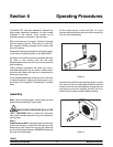
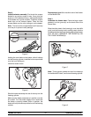
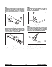
Step 1
Install thedriveshaft. Lubricate the groove andshaft
portion that comes in contact with the bearing on t he
beater drive shaft. Slide the seal over the shaft and
groove until it snaps into place. DO NOT lubricate the
hex end of the drive shaft.
Fill the inside portion of the seal with 1/4” more
lubricant and lubricate the flat side of the seal that fits
onto the rear shell bear ing.
Figure 3
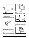
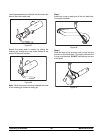
Insert the drive shaft into the freezing cylinder, hex end
first, and into the rear shell bearing until the seal fits
securely over the rear shell bearing. Engage the hex
end firmly into the drive coupling. Be sure the drive
shaft fits into the drive coupling without binding.
Figure 4