


13
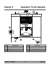
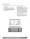
Model C707 Important: To the Operator
050112
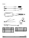
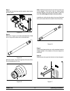
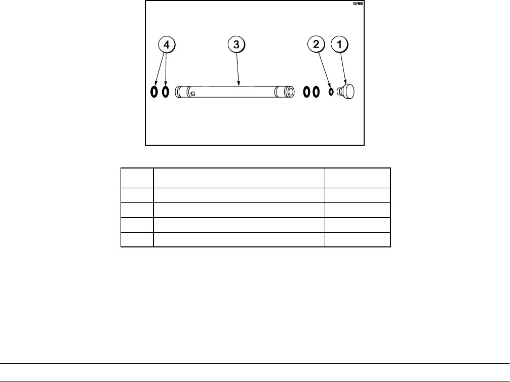
Feed Tube Assembly
The feed tube assembly serves two purposes. One end of the tube has a hole and the other end does not.
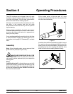
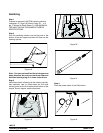
1. Normal Operation
During normal operation, the end of the feed tube
with the hole is placed into the mix inlet hole.
Every time the draw handle is raised, new mix and
air from the hopper flow into the freezing cylinder.
This keeps the freezing cylinder properly loaded
and maintains overrun.
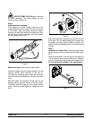
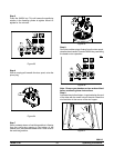
2. Long “No Sale” Periods
During long “No Sale” periods, the unit can be
placed into the Standby mode. This maintains
product temperatures below 40_F(4.4_C) in both
the hopper and the freezing cylinder, and helps
prevent overbeating and product breakdown.
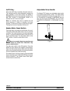
To place the unit into the Standby mode, press the
STANDBY key. Remove the air orifice. Lubricate
the o--rings located on the end of the feed tube
without the hole. Place that end of the tube into
the mix inlet hole.This will prevent any mix from
entering the freezing cylinder.
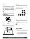
Note: The air orifice is used to meter a certain
amount of air into the freezing cylinder . The air
orifice maintains overrun and allows enough mix
to enter the freezing cylinder after a draw.
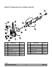
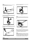
Figure 2
ITEM DESCRIPTION PART NO.
1 ORIFICE 022465-- 100
2 O-- RING-- 3/8 OD X .070 W 016137
3 TUBE A.--FEED--SS 5/32 HOLE X29429-- 2
4 O--RING--.643 OD X .077 W 018572