


5
Models RD30/RC25 To the Installer
Installation
Step 1
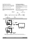
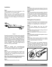
Install refrigeration lines from the dispenser to the
condensing unit. Do not create oil traps.
Note: For proper oil return, installation of horizontal
suction lines are to be sloped downward in the
direction of the condensing unit. The slope must be a
minimum 1/4” (.64 cm.) angle per 10 ft. (3.048 m.) of
line length.
Figure 1
Normally, any straight run of tubing must be supported
near each end of the run. Long runs require additional
supports. As a guide, 3/8” to 3/4” copper should be
supported every 5 ft. When changing directions, no
corner should be left unsupported. Supports should be
placed a maximum of 2 ft. in each direction from the
corner. If soft copper tube is used, make sure it is not
kinked or flattened. If hard drawn copper tubing is
used, use only long radius elbows.
Step 2
Braze the supplied quick connect/disconnect
couplings on the dispenser end of the refrigeration
lines. Couplings are supplied with the dispenser .
Step 3
Braze the quick connect/disconnect couplings and
access tees on the condensing unit end of the
refrigeration lines. Couplings and access tees are
supplied with the unit.
Note: Wrapa wetcloth aroundthe brasscoupling
bodies to prevent heat damage to the seal.
Step 4
Test the field constructed lines for leaks.
Step 5
Evacuate the field constructed refrigerant lines using
the access fittings brazed onthe c ondensingendof the
refrigeration lines.
Step 6
When the evacuation process is complete, relieve the
vacuum with 4 oz. (113 g.) of HP62 refrigerant per line,
for a total of 8 oz. (227 g.) This procedure will prevent
moisture contamination during dis penser and
condensing unit connection and complete t he total
charge.
Refrigeration Connections
Connect the refrigerant line quick connect/disconnect
couplings to the mating quick connect/disconnect
couplings on the dispensing and condensing unit.
Step 1
Remove the shipping caps from the quick
connect/disconnect coupling on the dispensing unit.
Step 2
Thoroughly clean and lubricate the mating surfaces of
the quick connect/disconnects.
Note: Use polyolester oil to lubricate the surfaces.
Step 3
Manually thread the coupling halves together to insure
proper mating of the threads.
Step 4
Using pr oper sized wrenches, tighten t he coupling
halves until the round, flat surfaces of inner coupling
bodies completely depress one another.
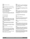
Step 5
Once the flat surfaces are completely depressed,
tighten the couplings an additional 1/4 turn. This step
is necessary to insure that the knife edge of the seal
seats into the brass seat of the coupling halves,
forming a leak--proof joint (metal seal).
Figure 2