


swru266
17/25
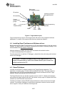
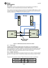
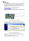
6 The Target Module
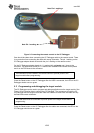
The target module is designed to allow flexible interfaces for many common types of
interfaces used in typical remote control applications. The target module uses a CC2533EM
RF reference design
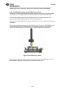
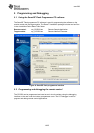
6.1 Target module hardware description
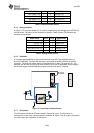
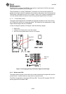
6.1.1 CC2533EM interface
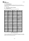
The signal names for the CC2533EM interface is detailed in Table 1:
EM header
RemoTI target
module signal
EM header
RemoTI target
module signal
P1_01 GND P2_01
P1_03 UART_CTS P2_03
P1_05 I2C_SCL P2_05
P1_07 UART_RX P2_07 VCC_EM
P1_09 UART_TX P2_09 VCC_EM
P1_11 I2C_SDA P2_11
P1_13 IR_OUT1 P2_13
P1_15 P2_15 EM_RESET
P1_17 LED0 P2_17 BUTTON
P1_19 GND P2_19 LED1
P1_02 P2_02 GND
P1_04 FLASH_CS P2_04
P1_06 IR_IN P2_06
P1_08 P2_08
P1_10 DD P2_10
P1_12 DC P2_12 USBM
P1_14 CSN P2_14 USBP
P1_16 SCLK P2_16
P1_18 MOSI P2_18 UART_RTS
P1_20 MISO P2_20
Table 1: EM module interface
Connector P1 and P2 are SMD, 2x10 pin row headers with 0.05in spacing. The part number
is TFM-110-02-SM-D-A-K-TR and it is produced by Samtec, www.samtec.com. The distance
between P1 and P2 is 1200 mils (centre to centre).