


swru266
3/25
List of Figures
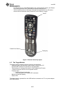
Figure 1: Remote Control Key layout .....................................................................................8
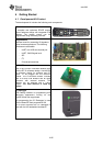
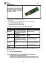
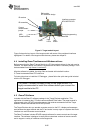
Figure 2: Target module layout..............................................................................................9
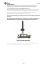
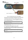
Figure 3: Assembled target module ..................................................................................... 10
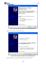
Figure 4: Connecting the target module for the first time (Windows XP) ............................... 11
Figure 5: Select automatic installation of software (Windows XP)......................................... 11
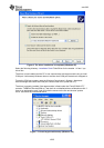
Figure 6: The driver installation is completed (Windows XP) ................................................12
Figure 7: Correct target module setup (Windows XP)........................................................... 12
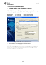
Figure 8: SmartRF flash programmer interface ....................................................................14
Figure 9: Connecting the remote control to the CC Debugger ..............................................15
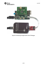
Figure 10: Connecting the target module to the CC Debugger ............................................. 16
Figure 11: USB interface selection with 0-ohm resistor ........................................................18
Figure 12: Serial flash interface details ................................................................................19
Figure 13: Changing polarity of IR control signal to active high.............................................20
Figure 13: Opening the remote control, step one .................................................................21
Figure 14: Opening the remote control, step two..................................................................21
Figure 15: Short pin 1(GND) and pin11 (SDA) ..................................................................... 22
Figure 16: Installing the EEPROM burner driver...................................................................22
Figure 17: Using the EEPROM burner software...................................................................23
List of Tables
Table 1: EM module interface..............................................................................................17
Table 2: Interface header pinout.......................................................................................... 19
Table 3: Debug Header pinout.............................................................................................19