


swru266
18/25
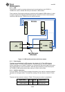
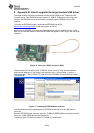
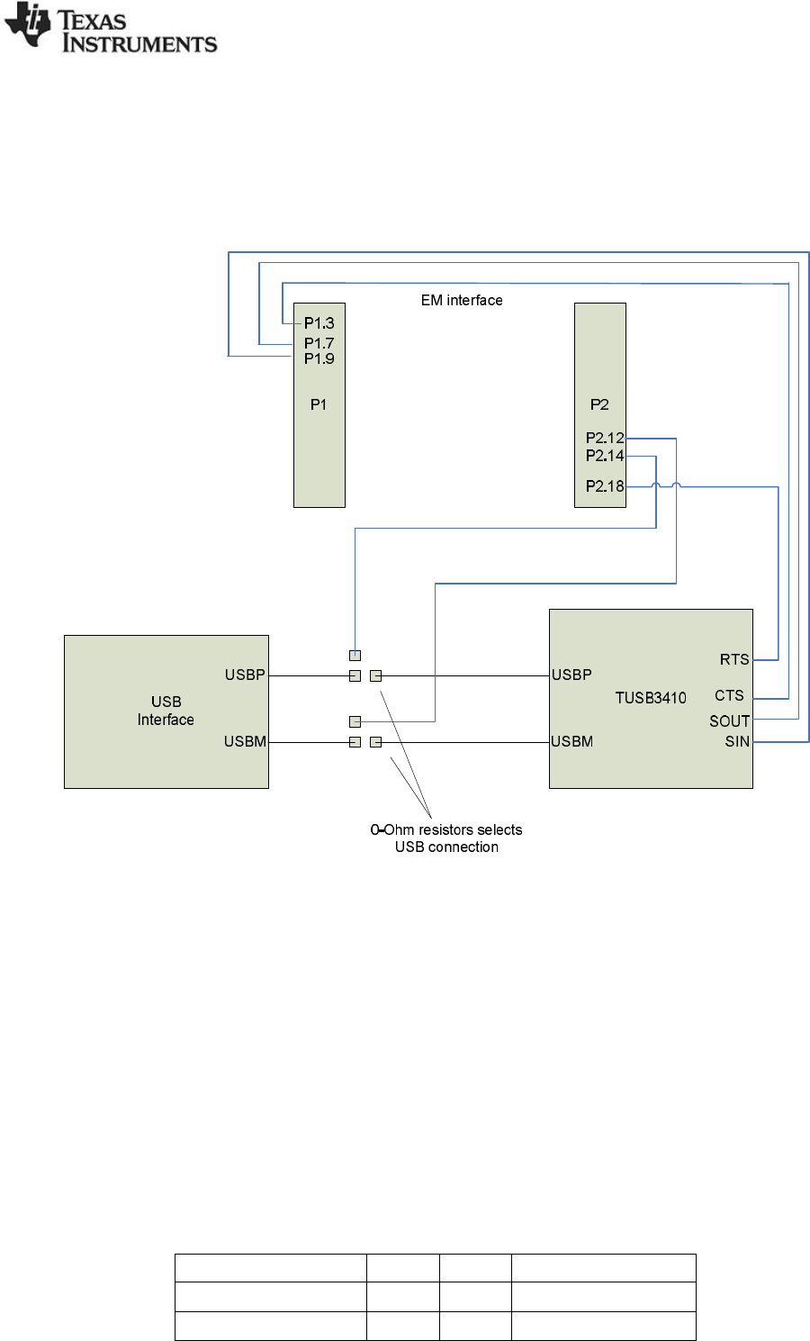
6.1.2 USB
The USB port is used for powering the board and for serial interface to the CC2533. A
TUSB3410 is used to translate the serial port interface to USB interface.
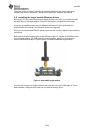
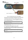
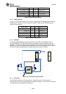
Future versions of the target module may use devices with integrated USB interfaces. In order
to support devices with integrated USB interface 0-ohm resistors are used to select between
interfacing USB directly to TUSB3410 and to the EM connector.
Figure 11: USB interface selection with 0-ohm resistor
6.1.3 Power supply
The board is powered from the USB connector, the voltage is 3.3V. The USB voltage is
regulated using a TPS79333 voltage regulator. The power supply of the board supports
current consumption up to 200mA. A jumper (J1) is mounted on the power supply line to allow
easy measurement of current consumption. Note that when measuring current consumption,
the TUSB3410 USB interface device may draw up to 15mA in active mode.
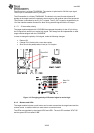
6.1.4 Interface connectors
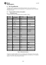
A 2x7 pin header, 2.54 mm pitch on the edge of the board (J4) is used for connecting external
equipment to the target module. The board has marking of the pin names as shown in Table
2.
The pinout of the connector is shown in Table 2. EM connector number in parentheses.
Signal name Pin # Pin # Signal name
GND 1 2 VDD
UART RX(P1.7) 3 4 UART TX(P1.9)