


Page 5
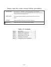
WARNING: Improper grounding can result in risk of electric shock.
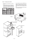
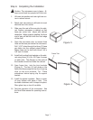
Step 4: Preparing the Trim Kit
(1) Attach the two vertical side trim brackets to the template as shown in Figure 3. Use two (2) #8 x
3
/8, Type B screws on each side.
(2) Mark the center line on bottom edge of the cutout.
(3) Hold template in front of cabinet cutout. Line up the bottom of the template with the bottom of the
cutout. Align the template notch with the centerline of the cutout.
(4) Mark the location of the three holes in the trim brackets on both sides. Set brackets and tem-
plate aside.
(5) Drill
1
/16" diameter starter holes.
(7) Remove template from trim brackets and discard. Set brackets and screws aside to be installed
later in the process.
Note: DO NOT attach trim brackets at this time. Continue to
Step 5: Installing the Ducts.
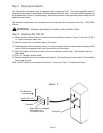
Step 3: Preparing the Electric
The Thermador microwave oven is equipped with a grounded cord. The wall receptacle must be
installed and grounded in accordance with the national electrical code. It can be installed anywhere in
the shaded area in Figure 1 (previous page). Electrical connections and grounding must comply with all
applicable local codes.
The electrical requirements for a separate circuit serving only this microwave oven are: 120V, 60Hz,
15Amp.
Figure 3
Align notch in template
with center line
of cabinet cutout
Screws #8
x
3
/8"
Centerline
Template
Trim Brackets