


User’s Manual
23
PART 1 AD268
5. I/O Allocation and Programming
5.3 Programming
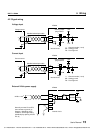
To read the A/D conversion data, there is no need to use special instruction. The A/D
conversion data are automatically stored in the assigned input registers (XW registers).
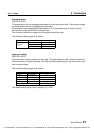
For example, when the AD268 is allocated to XW000 to XW007, the A/D conversion data of
each channel is stored as follows.
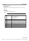
XW000 : Channel 1 A/D conversion data
XW001 : Channel 2 A/D conversion data
XW002 : Channel 3 A/D conversion data
XW003 : Channel 4 A/D conversion data
XW004 : Channel 5 A/D conversion data
XW005 : Channel 6 A/D conversion data
XW006 : Channel 7 A/D conversion data
XW007 : Channel 8 A/D conversion data
Therefore, in the user program, you can use these XW registers directly for the analog data
processing.
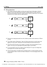
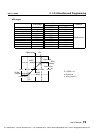
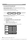
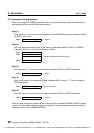
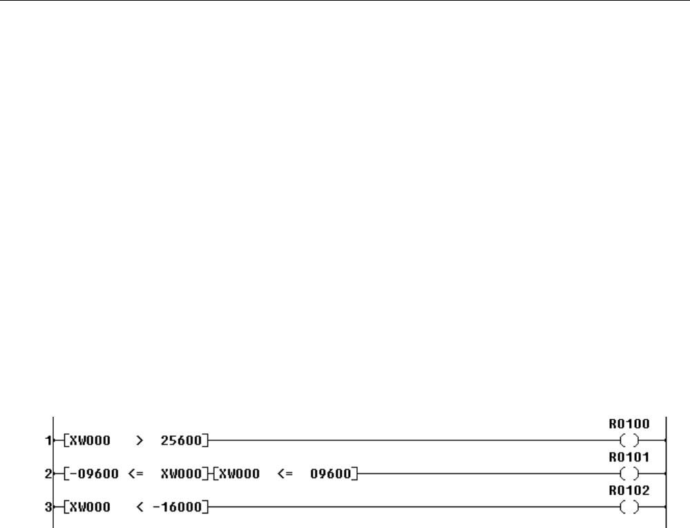
The program shown below is an example of simple comparison with the channel 1 analog data.
(±10V setting)
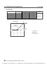
Line 1: When XW000 is greater than 25600 (channel 1 analog input is more than 8V), R0100
is set to ON.
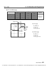
Line 2: When XW000 is in the range of -9600 to 9600 (channel 1 analog input is in the range
of -3V to 3V), R0101 is set to ON.
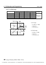
Line 3: When XW000 is less than -16000 (channel 1 analog input is less than -5V), R0102 is
set to ON.
CTi Automation - Phone: 800.894.0412 - Fax: 208.368.0415 - Web: www.ctiautomation.net - Email: info@ctiautomation.net