


32
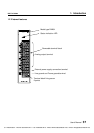
Analog I/O Modules (AD268 / DA264 / TC218)
7. Troubleshooting
PART 1 AD268
7. Troubleshooting
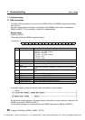
7.1 RAS information
The RUN LED is provided on the front of the AD268. When the AD268 is operating normally,
this LED is lit.
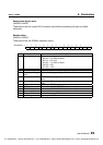
Also the module status information is provided in the AD268‘s buffer memory (addresses
H8030 to H8037). This information is useful for troubleshooting.
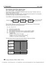
Module status:
(H8030 to H8037)
These data show the AD268’s operation status.
Bit position →
FEDCBA9876543210
0000
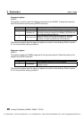
Bit Name Description
0 to 2 Input type Shows the input type.
000 (0) = 0 to 5V/0 to 20mA
001 (1) = 0 to 10V
010 (2) = 1 to 5V/4 to 20mA
100 (4) = ±5V
101 (5) = ±10V
3 to 5 - Reserved
6 Channel skip 1 when the channel skip is designated.
7 Input type setting
error
1 when the input type designation is invalid.
8 Wire break 1 when wire breakage is detected. (Effective only for 4 to 20mA
input)
9 Input limit 1 when the A/D conversion data is limited because of the range
over.
A MPU error 1 when the AD268’s processor is not normal.
B ROM status 1 when the AD268’s EEPROM is not normal.
C DP-RAM status 1 when the AD268’s DP-RAM (buffer memory) is not normal.
D- Reserved
E External 24V error 1 when the external 24Vdc is not normal.
F Initializing 1 during the AD268 is in initialization process.
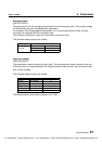
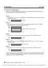
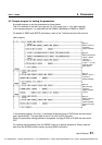
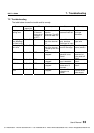
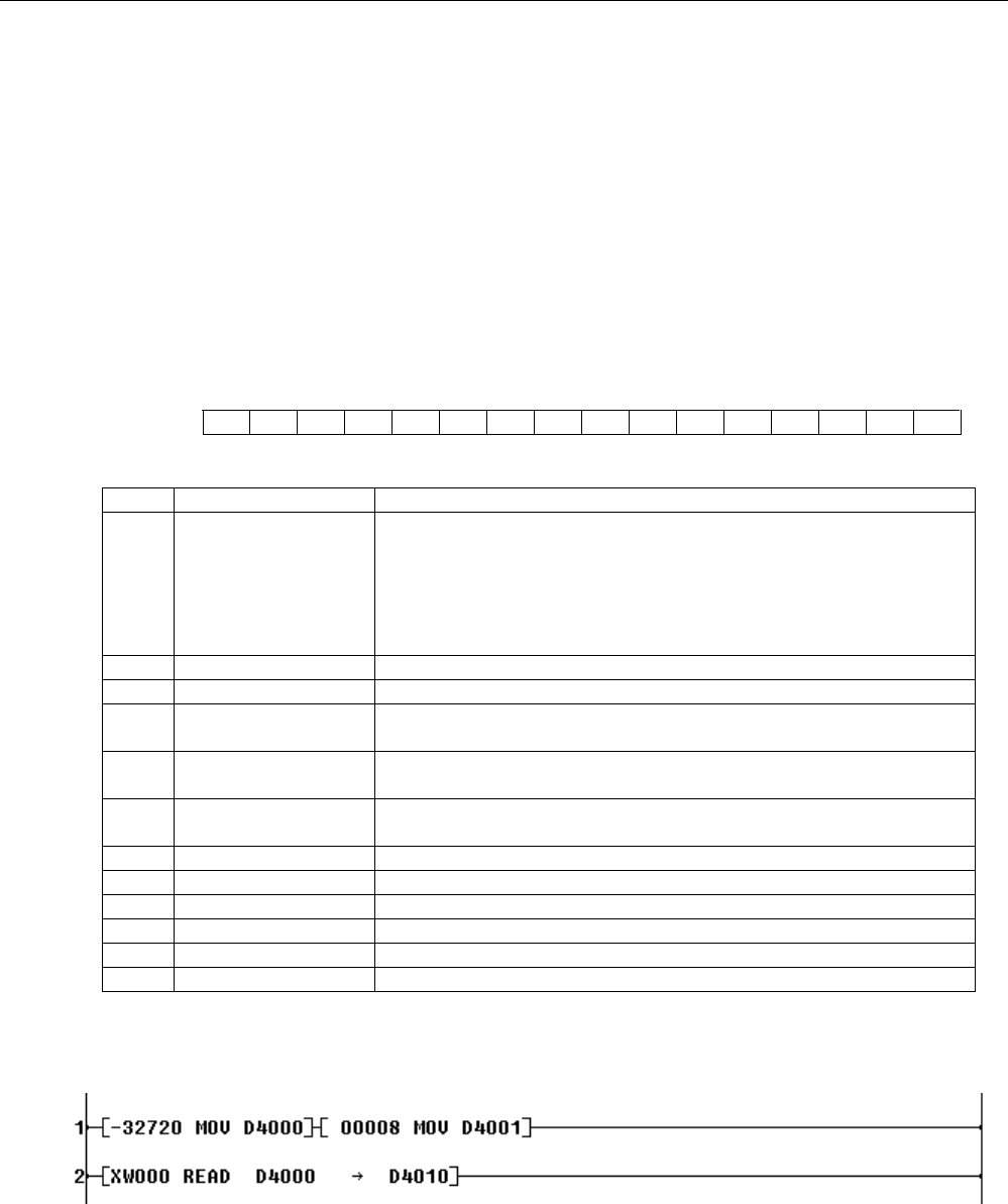
A sample program to read the module status information is shown below.
By the above sample program, the module status information for each channel is read from the
AD268, and stored in D4010 to D4017.
(In this sample program, it is assumed that the AD268 is allocated to XW000 to XW007)
(H8030)
CTi Automation - Phone: 800.894.0412 - Fax: 208.368.0415 - Web: www.ctiautomation.net - Email: info@ctiautomation.net