


RLC-SVD03A-EN 51
Module Power and Miscellaneous I/O
2. Has its negative terminal tied to chassis ground.
If the intended source does not meet the above requirement, an isolation
module must be used
The 4-20mA/2-10VDC inputs may be tested in the following ways:
1. Enable External Chilled Water Setpoint and/or External Current Limit Set-
point in the Operator Settings Menu. Advance display to Active Chilled
Water Setpoint or Active Current Limit Setpoint to observe the respective
setpoint in the Chiller Report.
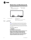
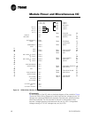
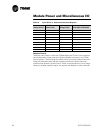
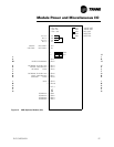
2. With all wiring in place, apply an external voltage or current to the Exter-
nal Chilled Water Setpoint inputs (TB1-4 & 5) or the External Current Limit
Setpoint (TB1-7 & 8). The voltage measured at the terminals and the
resulting setpoint, as read on the CLD, should agree with the Table 17 for
Chilled Water Setpoint inputs and Table 18 for Current Limit Setpoints
inputs. Be sure to wait long enough when reading the display as the val-
ues are slew rate limited.
3. Disconnect all wiring to these inputs. The setpoints should slew back to
the chiller's Front Panel settings.
4. Disconnect all wiring and install fixed resistors of values near those
shown in the following tables across TB1-3,5 or TBl-6,8. The resulting set-
points should agree with the table values.
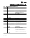
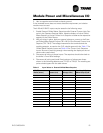
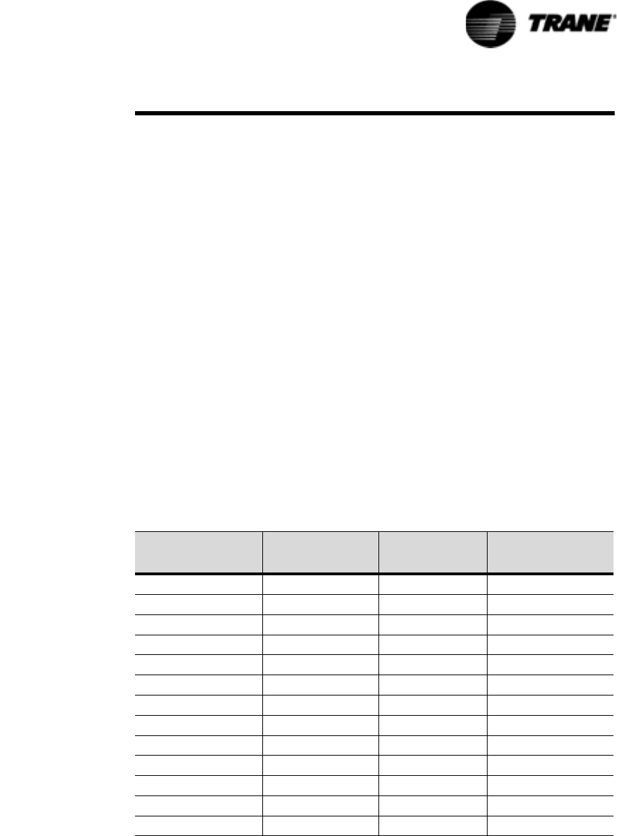
Table 17 Input Values vs. External Chilled Water Setpoint
INPUTS
Resist (ohms)
Current (ma) Voltage (Vdc)
Resulting Chilled
Water Setpt (F)±4F
94433 4.0 2.0 0.0
68609 5.2 2.6 5.0
52946 6.5 3.2 10.0
42434 7.7 3.9 15.0
34889 8.9 4.5 20.0
29212 10.2 5.1 25.0
24785 11.4 5.7 30.0
21236 12.6 6.3 35.0
18327 13.8 6.9 40.0
15900 15.1 7.6 45.0
13844 16.3 8.2 50.0
12080 17.5 8.8 55.0
10549 18.8 9.4 60.0