


RLC-SVD03A-EN 73
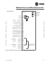
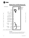
Module Power and Miscellaneous I/O
Binary Inputs
The binary inputs shown in Table 22 all use the same basic circuit. A pullup
resistor to the 12V power supply is connected to the higher numbered input
pin. The lower numbered pin is connected to ground. The voltage between
the two pins is sensed by the microprocessor To check the input, measure
the voltage between the two associated pins. With the external switch open,
approximately 12 Vdc should be measured. With the switch closed, 0 Vdc
should be measured.
Temperature Inputs
These inputs use Trane's standard thermistor,. an NTC device giving 10,000
ohms at 25 C (75 F). Refer to Temperature Sensor Checkout, Table 4, for a
table of temperature vs., resistance vs. voltage.
Three measurements can be made:
1. With the probe connected, the voltage across the input terminals may be
measured. The voltage should agree with the table values in the Temp er-
ature Sensor Checkout Procedure on page 15.
2. The probe may be disconnected from the module and its resistance mea-
sured. It should agree with the table values.
3. With the probe disconnected, the terminal voltage may be measured
with a high impedance voltmeter. It should be between 4.975 and 5.025
Vdc. If the meter loads the input, a slightly lower voltage may be
expected.
Refer to Temperature Sensor Checkout for more details.
Current Inputs
The following tests may be used to check a current input circuit:
1. With the compressor off, the AC voltage across the terminals with the
current transformer connected should read 0 V The corresponding cur-
rent as read on the CPM display should read 0.
2. With the compressor on, the AC voltage across the terminals should
agree with the data of Table 8. The %RLA read on the CPM display will
depend on the setting of the gain switch. If the gain switch is set to 11111,
the percent CT rating values should agree with the display. For any other
switch setting, the gain factor as found in Table 9 must be taken into
account using one of the following procedures:
• Start with the displayed %RLA. Multiply by .67 and divide by the gain
where the gain is found in Table 16. The result is the percent CT rating.
Use this and the Table 8 to find the corresponding terminal voltage.
• Start with an actual current measurement (such as from a clamp-on
ammeter). Determine which CTs are being used and use the Table 8 to
find the corresponding terminal voltage and percent CT rating. Multiply
the percent CT rating by the gain and divide by.67 to find the %RLA that
should be displayed.
NOTE: If the MCSP gain switch and CPM gain setting do not agree, a
diagnostic will be generated and the MCSP will continue operating using a
default gain setting of 00000 (max gain). This will result in the MCSP thinking