


58 RLC-SVD03A-EN
Module Power and Miscellaneous I/O
Electronic Expansion Valve Module (EXV) (1U3)
ƽ WARNING
Live Electrical Components!
During installation, testing, servicing and troubleshooting of this
product, it may be necessary to work with live electrical
components. Have a qualified licensed electrician or other
individual who has been properly trained in handling live
electrical components perform these tasks. Failure to follow all
electrical safety precautions when exposed to live electrical
components could result in death or serious injury.
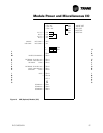
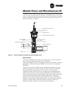
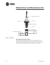
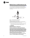
Valve Operation
The electronic expansion valve is an electronic flow device that replaces the
thermostatically controlled expansion valve and liquid line solenoid. A
sectional view of the valve is shown in Figure 16 and Figure 17.
The control method uses two sensors that measure the temperature
difference between the inlet and outlet evaporator refrigerant temperature.
This enables the system to control the temperature difference and maintain
superheat.
The SEO-70 and SEO-100 valves were used on units until November 1, 2003.
All units built after that date will have a SEHI-100 valve installed.
The module for the SEHI is different because the new valve uses a two coil
instead of three. The locations of the keying pins are different on the module.
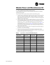
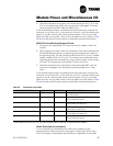
Design Sequence Information, digit 10-11 of the unit model number.
RTWA/UA A0 - E0 SEO Valve
RTWA/UA F0 and later SEHI Valve
RTAA A0 - P0 SEO Valve
RTAA Q0 and later SEHI Valve
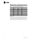
NOTE: For units with remote evaporator use 16 AWG wire.
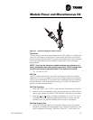
SEO-70 and SEO-100 Valve
The valve is a stepper-motor type, direct acting valve. It uses a three-phase
motor (not to be confused with3-phase AC), with each phase having 40 ohms
of resistance.
The supply voltage (24 VDC) is switched on and off to each phase, to step the
valve open or closed. Each step is 0.0003" of stroke, with a full stroke of 757
steps.
The motor's rotary motion is translated into linear movement through a lead
screw and drive coupling arrangement. A clockwise rotation of the motor
shaft creates a downward movement of the drive coupling. This presses the
pushrod and piston against the return spring, opening the valve. A counter-
clockwise rotation of the motor shaft retracts the drive coupling. The return
spring moves the piston and pushrod in the closing direction.