


RLC-SVD03A-EN 75
Module Power and Miscellaneous I/O
I/O Terminals
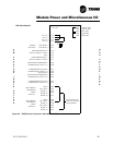
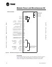
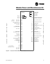
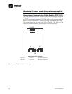
For the checkout of the I/O, refer to the block diagram of the MCSP module in
Figure 22 and the Chiller Wiring Diagrams for both high and low voltage
circuits. All voltages are measured differentially between terminal pairs
specified unless otherwise indicated. The first terminal in the pair is the
positive (or hot) terminal. Voltages given are nominals and may vary by ±5%.
Unregulated Voltages (unreg) or 115 VAC voltages may vary by ±15%.
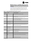
Table 22 Compressor Module Normal Terminal Voltages (1 U4 and 1 U5)
Te r mi nal
Designation
Description
of Circuit
Normal Terminal Voltages
for Various Conditions
J1-4 to 3
or J1-2 to 1
IPC Communications 19.2 kbaud serial data, 5 volt signal level.
Refer to Interprocessor Communication Interface.
J2-2, 1 Manufacturing Address Use
Only
+5 VDC No connection intended.
J3-7, 6 External Circuit Lockout Open = 12 VDC: ckt lockout
Closed 0 VDC: normal
(ckt. lockout' only if feature is enabled in Service Settings)
Must be jumpered if this feature is not used.
J3-4, 3 Transition Complete Open = 12 VDC: pre-transition
Closed = 0 VDC: transition complete
(only used with reduced voltage starters)
J3-2, 1 Not Used Must be jumpered.
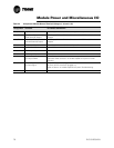
J4-5, 4 Saturated Condenser
Refrigerant Temp
Refer to Temperature Sensor Checkout.
J4-3, 1 Entering Oil Temperature Refer to Temperature Sensor Checkout.
J5-7, 6 Phase A Current
Transformer Input
Input for 100-400:0.1 Ratio CT using digital VOM
in diode test mode open circuit input should read between 1.0 to 1.5
Volts.
Refer to Current Transformer Checkout.
J5-5, 4 Phase B Current
Transformer Input
Same as above.
J5-2, 1 Phase C Current
Transformer Input
Same as above.
J6-1 or 2
to J6-4 or 5
Input Power 115 VAC, Refer to Power Supply in Module.
Power and Miscellaneous I/O.
E3, E4 Compressor Motor
Winding Temp
Thermostat.
Internally powered Isolated input.
Open = 16 Vac: high temp
Closed = 0 Vac: Ok temp
E5 to High Pressure Externally powered isolation transformer input,
J6-4 or 5 Cutout Input 2 VA, 115 Vac 115 volts input: normal 0 volts: trip
E5, J7-3 Compressor Contactor
Output
Normally open contact, closes for compressor start
Uses same power input as High Pressure Cutout input above.
J7-1, E6 Crankcase Heater Output Normally closed contact, powers crankcase heater when compressor is
off.
J7-5,6 Transition Command Output Normally open contact, closes to initiate Wye to Delta Starter transition if
configured for Reduced Voltage start.