


II. a - INTRODUCTION:
This manual applies to the following Traulsen
models only:
TE036HT, TE048HT, TE060HT, TE065HT, TE072HT
TE084HT, TE096HT, TE110HT, TE125HT &
TE139HT
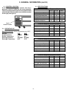
II. b - MODEL DESIGNATIONS:
Position 1: TE = Traulsen Equipment Stand
Position 2: 036 = 36” Long Model
048 = 48” Long Model
060 = 60” Long Model
Position 3: HT = Refrigerator
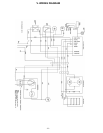
II. c - WIRING DIAGRAM:
Refer to the wiring diagram for any service work
performed on this unit. A copy is located on the unit
when shipped. Should you require another copy, or a
wiring diagram for an older production unit, please
contact Traulsen Service at (800) 825-8220, and
provide the model and serial number of the unit
involved (this information is located on the serial
tag, see page one).
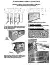
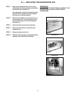
II. d - INSTALLATION:
Generally TE-Series refrigeration products are installed
by the dealer, or others contracted by the dealer or
owner. Detailed installation instructions are included
along with each unit when shipped.
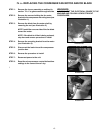
II. e - CLEANING:
Detailed cleaning instructions are included with each
unit, however special care MUST be given to the
condenser coil. The condenser coil must be cleaned
at a minimum of every six months. This can be done
with a vacuum cleaner using a brush attachment, or a
stiff brush or wisk broom. For more information please
refer to
“Section V.a” of the TE-Series Owner’s
Manual.
II. f - TOOL REQUIREMENTS:
For most jobs a standard set of hand tools, a VOM and
AC current tester, along with a temperature tester or
thermometer are adequate. However in some cases
the following additional tools may be required as well:
• Refrigeration Guage Manifold
• Refrigeration Reclaiming Equipment
• Acetylene Torch
• Anti-Static Grounding Kit (TL 84919)
• Nitrogen Bottle With Gauges
• Thin 5/16” Open End Wrench
• Refrigerant Reclaim Unit
II. GENERAL INFORMATION
-2-
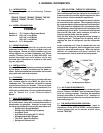
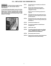
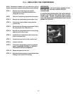
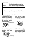
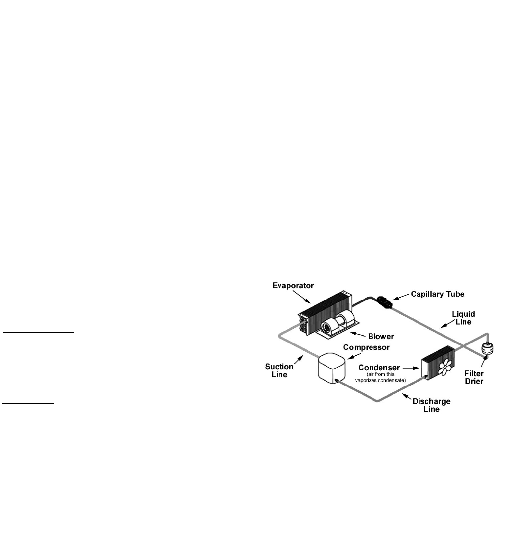
II. g - REF’N SYSTEM - THEORY OF OPERATION:
The refrigeration system is the mechanism whereby
heat is transferred from the cabinet to the outside air.
It works under the principle that the heat moves from
hot to cold as it tries to establish equilibrium.
The microprocessor control signals a need for heat to
be removed from the cabinet. The compressor begins
by compressing the refrigerant gas as it is discharged.
The high pressure refrigerant now circulates through
the condenser, removing heat from the refrigerant and
condensing it into a liquid. From there the refrigerant
flows to the filter drier which removes all traces of
moisture and particles from the system.
After the filter drier, the refrigerant passes through a
“metering device.” Traulsen uses a capillary tube to
regulate the flow of refrigerant into the evaporator
coils.
In the evaporator coil, heat is transferred from the
cabinet to the refrigerant, which changes from a cold
liquid to a warm low pressure gas. When the desired
cabinet air temperature has been reached, the
microprocessor control shuts off the compressor.
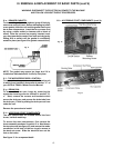
II. h - AIR FLOW REQUIREMENTS:
To assure optimum performance, the condensing unit
of your Traulsen unit MUST have an adequate supply
of air for cooling purposes. Therefore, the operating
location must allow a minimum of 12” clearance in
front of the louvers to allow for unrestricted air flow to
the condensing unit.
II. i - THE MICROPROCESSOR CONTROL:
For detailed information on replacement, repair or
adjustment of the INTELA-TRAUL
®
microprocessor
control please refer to it’s service manual (form
number TR35705).
Fig. 1 - The Refrigeration System
TE060HT