


TABLE OF CONTENTS
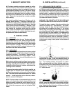
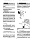
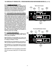
The serial tag is a permanently affixed sticker on
which is recorded vital electrical and refrigeration data
about your Traulsen product, as well as the model
and serial number. This tag is located in the upper
right interior compartment on all reach-in/pass-thru
and roll-in/roll-thru refrigerator, freezer and dual-temp
models. For hot food and proofer models, this tag is
located on the top of the unit behind the louvers to
protect it from the heat.
I. THE SERIAL TAG
-1-
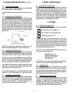
FORT WORTH, TX.
SERIAL MODEL
VOLTS Hz PH
TOTAL CURRENT AMPS
MINIMUM CIRCUIT AMPS
MAXIMUM OVERCURRENT PROTECTION AMPS
LIGHTS WATTS
HEATERS AMPS
REFRIGERANT TYPE OZ
DESIGN PRESSURE HIGH LOW
REFRIGERANT TYPE OZ
DESIGN PRESSURE HIGH LOW
370-60294-00 REV (A)
READING THE SERIAL TAG
• Serial = The permanent ID# of your Traulsen
• Model = The model # of your Traulsen
• Volts = Voltage
• Hz = Cycle
• PH = Phase
• Total Current = Maximum amp draw
• Minimum Circuit = Minimum circuit ampacity
• Lights = Light wattage
• Heaters = Heater amperage (Hot Food units only)
• Refrigerant = Refrigerant type used
• Design Pressure = High & low side operating
pressures and refrigerant charge
• Agency Labels = Designates agency listings
VII. PROOFER & PROOFER/RETARDER MODELS
a-Installation Page 6
b-Proofer Operating Instructions Page 6
c-Operating The Dial Humidistat Page 6-7
d-Retarder Operation Page 7-8
e- Care of Water Tank & Heating Elements Page 8
f-Interior Arrangements Page 8
VIII. EVEN-THAW MODELS
a-Application Overview Page 9
b-Product Loading Guidelines Page 9
c-Starting An Even-Thaw Cycle Page 9
d-Conclusion Of Even-Thaw Cycle Page 9
e-Interior Arrangements Page 9
f-Frequently Asked Questions Page 9-10
IX. FISH FILE MODELS
a-Fish File Application Page 10
b-Special Installation Note Page 10
c-Drawer Pans Page 10
d-Product Loading Page 10
e-Cleaning Page 10
X. BLAST FREEZER MODELS
a-Blast Freezer Application Page 11
b-Special Installation Note Page 11
c-Interior Arrangements Page 11
d-Blast Freezing vs. Blast Chilling Page 11
e-Normal Operation Page 11
f-Defrost Page 11
g-Blast Chill Operation Page 11
h-Proper Packaging Page 11
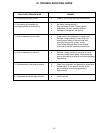
XI. TROUBLE SHOOTING GUIDE Page 12
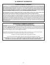
XII. WARRANTY INFORMATION Page 13
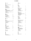
XIII. INDEX Page 14
I. THE SERIAL TAG Page 1
II. RECEIPT INSPECTION Page 2
III. INSTALLATION
a-Location Page 2
b-Packaging Page 2
c-Installing Legs or Casters Page 2
d-Shelf Pins Page 2
e-Roll-In Model Installation Page 3
f-Installing The Condensate Evaporator Page 3
g-Remote Installation Page 3
h-Cord & Plug Page 3
i-Power Supply Page 4
j-Wiring Diagram Page 4
k-Compressor Hold Down Provisions Page 4
l-Clearance Page 4
IV. CARE & MAINTENANCE
a-Cleaning The Condenser Page 4
b-Hinge Replacement Page 4-5
c-Replacing The Gaskets Page 5
d-Cleaning The Exterior Page 5
e-Cleaning The Interior Page 5
V. MISC. OPERATIONS
a-Adjusting The Shelves Page 5
VI. OTHER
a-Service Information Page 5
b-Spare Parts Page 5
c-Warranty Registration Page 5