-6-
VII. SPECIALTY PRODUCTS - PROOFER/PROOFER RETARDER MODELS
VII. a - INSTALLATION:
MECHANICAL CONNECTION: For plumbing, connect
water supply to inlet strainer as marked on top of cabi-
net. This connection should be made with a 3/8” male
NPT connector. Water supply pressure should 50 to
80 PSI for best operation.
The drain connector located at the top rear of the cabi-
net should be made with a 1/2” NPT drain line which
should be connected to either a floor drain or sink
connection. A back flow prevention device (vacuum
breaker) must be used in the water supply line to this
unit.
CAUTION: Any restriction in the drain line could cause
overflow conditions. It is imperative that the 1/2” NPT
fitting be used and the drain line not be reduced in
diameter. If plastic is used, care must be taken to avoid
collapsing the tubing.
ELECTRICAL CONNECTIONS: The Traulsen Proofer
model requires two separate electrical connections.
The first connection is to operate the heater and hu-
midifier. This connection will either be 208/60/1 or 230/
60/1.
Please note electrical information for each cabinet at
given voltage.
PRI132H
Voltage 208/60/1 230/60/1
Amps 21.5 24.0
Watts 4400 5500
PRI232H
Voltage 208/60/1 230/60/1
Amps 30.0 33.5
Watts 6100 7700
PRI332H/PRR232HUT
Voltage 208/60/1 230/60/1
Amps 30.0 33.5
Watts 6100 7700
The second connection is a standard 115/60/1 to oper-
ate the control circuits. When connecting a 115 volt
power supply to the cabinet, be sure to connect neu-
tral to white cabinet wire and “live” wire to cabinet
black wire. Reversal of polarity will cause inconsis-
tent operation. Electrical information on this connec-
tion is the same for each proofer cabinet.
PRI PRR
Voltage 115/60/1 115/60/1
Amps 3.0 13.5
Watts 500 2100
VII. b - PROOFER OPERATING INSTRUCTIONS:
The Traulsen proofer is designed to automatically flush
out the water tank once every 24 hours. The operator
should select a flush time when the unit is not proof-
ing.
This unit displays the time of day and temperature of
the unit simultaneously. When the proofer is activated
both the time of day and the flush time must be ad-
justed.
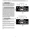
SETTING THE CLOCK:
A-TIME OF DAY - When the unit is initially activated
the time of day is shown as 12 p.m. Use a pointed
object and insert into the fast or slow openings to ad-
vance the time of day. NOTE: P.M. is indicated by a
LED dot in the upper left corner of the time display.
B-FLUSH TIMER - Insert a pointed object into the flush
opening to display the flush time. While the flush time
is being displayed the fast or slow openings should
be used to advance to the desired flush time.
Once the time clock has been set the unit is ready for
operation:
1) Adjust the temperature control to the desired
temperature
2) Adjust the humidity control to the desired
humidity.
To activate the unit turn ON the lower switch and then
the control switch. Let the unit reach the temperature
selected.
HEATER THERMOSTAT: When adjusting the heater
thermostat, keep in mind that the heater element does
not cool instantly. There is an override in temperature
of approximately 9 to 12 degrees. This may vary, de-
pending on location, and the thermostat may have to
be adjusted. Once the unit is warmed up to the de-
sired temperature, you will notice that the tempera-
ture will stabilize and not vary significantly.
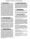
VII. c - OPERATING THE DIAL HUMIDISTAT
The Traulsen humidifier is controlled by a dial humi-
distat (R.H.). Adjust dial selector for proper level of
humidity. The humidity setting should be 2 to 3 per-
cent below desired setting. The humidifier, in addi-
tion to creating humidity in the cabinet, will also cre-
ate heat. Activate the power switch to the control
heater element. The level of desired humidity should
be based upon product being proofed. If however, you
are utilizing one level of humidity for all products, it is
not necessary to readjust the humidistat each time the
cabinet is turned on.


