


Electrical connections
Before connecting the appliance, check that the vol-
tagequoted onthe rating plate - that is, the nominalvol-
tage of the appliance - corresponds to the available
mains voltage. The rating plate can be found on the
lower housing of the ceramic glass hob.
The mains connection must be carried out by an expert
electrician. The VDE-regulations and the valid pre-
scriptions by the local power suppy boards have to be
compiled with.
Prior to connection it should be checked whether the
voltage stated on the type plate -- i.e. the nominal vol-
tage of the appliance and of the oven/control box -- is
identical with the prevailing mains voltage. The type
plate ist located on the hobs bottom.
The heating element voltage amounts to 230 V ~. The
appliance will also perfectly perform with the former
mains voltage of 220 V ~.
The mains connection must be carried out in a waythat
an all--pole insulating device is existing with a contact
opening of at least 3 mm, e.g. LS--automatism, earth--
leakage circuit--breaker or fuse.
A wire of type H05VV-F or of higher rating is to be used
as supply cable.
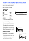
The mains terminal is located in the bottom of the
appliance behind a covering slide. It can be opened
with a screw driver (pict.).
According to existing mains voltage the appliance has
to be connected in correspondence with the diagrams
of connecting possibilities. The bridges of the terminal
board are to be changed accordingly, if need be.
The protective conductor is to be connected to terminal
. The protective conductor must be longer than live
leads.
The cable connections have to be established as
prescribed and the terminal screws be firmly
tigh-
tened.
Afterwardsthe supplycablehas to besecured by strain
relief device and the covering slide must be closed by
firmly pressing down (until it enganges).
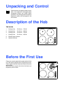
Prior to first use remove any possibly existing labels
and protective film from the ceramic glass plate or the
frame of the hob.
After connecting the electrical supply, all cooking
zones should be briefly switched on one after the
other at their maximum power, in order to test
whether they are operational.
strain relief device
Mains terminal
in the bottom of the hob
L1 N
5
Connecting possibilities
1 2 3 4
L1 L2 N
51 2 3 4
L1 L2 L3 N
51 2 3 4
L1 L2
51 2 3 4
L1 L2 L3
51 2 3 4
(L3)
1 L + N
2 L + N
3 L + N
2 L
3 L
230 V ~
400 V 2 N ~
400 V 3 N ~
230 V 2 ~
230 V 3 ~
changing brid-
ges of the ter-
minal
3 x 6 mm
2
(30 A)
4 x 2,5 mm
2
(20 A)
3 x 4 mm
2
(32 A)
5 x 2,5 mm
2
(16 A)
4 x 2,5 mm
2
(20 A)