


Installation & Service Manual TLM, TLF, TLD
Page 13
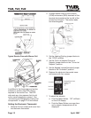
c. Push the Up or Down Button until the
desired setpoint is displayed. (TLM =
22°F, TLF = 33°F or TLD = 22°F)
d. Push the Menu Button.
8. To adjust the differential:
a. Push the Menu Button. “SP” will flash
on the LCD display.
b. Push the Down Button until “DIF” is
shown on the LCD display.
c. Push the Menu Button one more time
and a differential number will be
displayed.
d. Push the Up or Down Button until
the desired differential setting is
displayed. (TLM = 4°F, TLF = 1°F
or TLD = 4°F)
d. Push the Menu Button.
With the cooling mode selected, the
differential is ABOVE the setpoint. The relay
will be energized and the LED indicator will
illuminate when the temperature reaches the
differential setting. When the temperature
drops to the setpoint, the relay and LED
indicator will de-energize and refrigeration
will stop.
The settings above are specific to TYLER
service cases. Other applications will require
different setpoints and differentials.
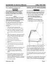
Electrical Procedures
Electrical Considerations
CAUTION
Make sure all electrical connections at
components and terminal blocks are tight.
This prevents burning of electrical termi-
nals and/or premature component failure.
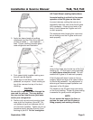
NOTE
The ballast box is located at the lower left
rear corner of the case. It houses ballasts
and terminal blocks.
Case Fan Circuit (TLD only)
This circuit is to be supplied by an
uninterrupted, protected 120V circuit. The
case fan circuit is not cycled on this case.
Ambient Fan Circuit
All TL cases have an ambient fan circuit. This
circuit is supplied by an uninterrupted, protect-
ed 120V circuit. The ambient fan circuit is not
cycled.
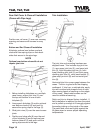
Fluorescent Lamp Circuit
TL case lighting is supplied by T-8 electronic
ballast lights. It is controlled by a light switch
in each case. The standard lighting is 1-row
of horizontal canopy lights.
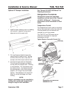
Anti-Sweat Circuit
All anti-sweat heaters are wired directly to
the main power supply so they can operate
at all times.
Defrost Information
See “General (UL/NSF) I&S Manual” for
operational descriptions for each type of
defrosy control.
Defrost Control Chart
TLM/TLF Defrost Option Settings
Defrost
Defrost Defrosts Duration Term.
Type
Per Day (Min) Temp.
Off Time 2 54 -----
TLD Defrost Option Settings
Defrost
Defrost Defrosts Duration Term.
Type
Per Day (Min) Temp.
Off Time 4 34 -----
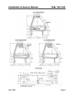
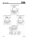
Thermostat and sensor locations are shown
on pages 11 and 12 of this manual.
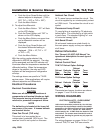
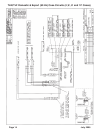
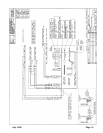
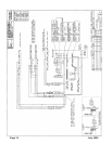
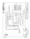
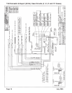
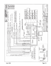
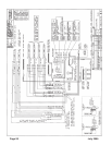
WIRING DIAGRAMS
ELECTRICIAN NOTE - OVERCURRENT
PROTECTION
120V circuits should be protected by 15 or 20 Amp
devices per the requirements noted on the cabinet
nameplate or the National Electrical Code, Canadian
Electrical Code - Part 1, Section 28. 208V defrost
circuits employ No. 12 AWG field wire leads for field
connections. On remote cases intended for end to
end line-ups, bonding for ground may rely upon the
pull-up bolts.
The wiring diagrams on pages 14 thru 21 will
cover all TLM, TLF and TLD case circuits.
July, 2005