


Installation & Service Manual TLM, TLF, TLD
Page 27
SERVICE INSTRUCTIONS
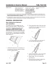
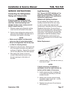
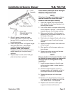
Connecting the Refrigeration
Piping and Components
WARNING
Be sure to position a flame and heat-
resistent shield over the bottom of the
case liner. Heat from brazing could
damage the liner and/or cause personal
injury or death from fire.
1. Remove screws and refrigeration piping
cover from the left bottom of the case.
2. Position loose refrigeration piping and/or
optional valves between the open lines in
the bottom and upright of the case.
NOTE
• Make sure all sensor and thermostat
wires are clear of areas being heated.
• Mount all refrigeration lines off the floor
to allow for cleaning access.
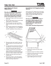
3. Apply flux to all joint ends. Starting at one
end, thoroughly heat each new pipe joint
and braze it together. Repeat this process
until all new pipe joints have been brazed.
4. After piping has cooled, route and
connect thermostat and sensor wires
through openings in the bottom of
the case.
Light Servicing
See “General (UL/NSF) I&S Manual” for
preventive maintenance, T-8 lamp, fan
blade and fan motor (TLD) replacement
instructions replacement.
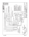
Ballast and Lighting Locations
All light ballasts are located in the rear
raceway channel behind the rear cover.
In order to retain safety approval with
Underwriter’s Laboratory and the Canadian
Standards Association, the mounting of
electrical components and interconnecting
wires must not deviate from the following
instructions. Only qualified personnel are
authorized to install the accessory items.
TYLER Refrigeration recommends you
order all components from its Service Parts
Department.
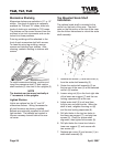
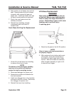
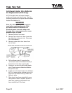
Ballast Replacement
1. Remove screws (1) and rear rail cover (2)
from rear of case.
NOTE
If tappit screws are not available, a
starwasher should be used between the
ballast and the heads of the screws.
2. Install required number of ballasts (3)
in rear electrical raceway (4) with two
screws (5) each.
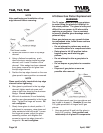
3. Identify and connect required wiring
harnesses (upper, lower, etc...) to the
ballast connectors (6).
4. Replace rear rail cover (2) and secure
with screws (1).
September, 2004