


2015WC/2015WCOL Wine Captain
®
www.U-LineService.com 10 02/2005
™
Installation Instructions
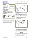
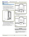
Preparing Door
Note: Door is not attached. It
is in a separate box inside the
unit box and taped to the
unit.
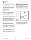
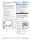
1. Lay door on a clean, flat
surface with the gasket
facing up.
2. Pull gasket completely out
of the groove. Start in the
middle and pull outward,
moving toward the edge
(see
Figure 16
). This may take some force.
Note: Lay gasket flat on a clean surface to avoid
disturbing interior magnet.
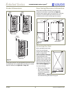
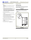
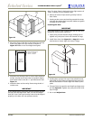
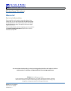
Checking Overlay Fit
1. Turn door over and lay overlay frame on front side of
door. Make sure frame is fully seated on all four sides.
See Figure 17.
2. Visually check for gap between frame and glass. If there
is an objectionable gap, follow steps under Applying
Foam Tape to Overlay Frame. If there is little or no gap,
continue to Attaching the Overlay Frame.
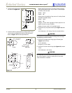
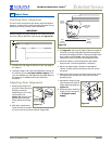
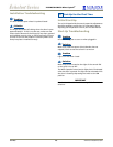
Applying Foam Tape to Overlay Frame (If required)
1. Cut foam tape into four pieces, two pieces the width
of the overlay frame and two pieces the height of the
overlay frame.
2. Remove the adhesive protection strip from one piece of
the foam tape and align to the edge of the overlay
frame as shown in
Figure 18
, adhering the foam tape
to the overlay frame.
3. Trim each piece of tape immediately after application.
Do not allow any overlapping of the foam tape.
Damage to the overlay frame can occur if the foam tape
is not trimmed properly.
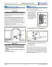
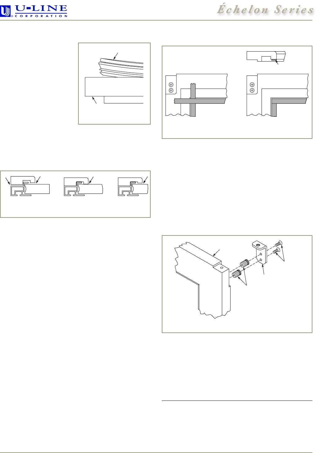
Attaching the Overlay Frame
1. Tap nylon inserts into the top holes drilled in the
overlay frame. Use two #6 screws to attach top pivot
bracket to the overlay frame (see Figure 19).
2. If a user-supplied cabinet handle will be used, attach its
hardware to the overlay frame at this time.
IMPORTANT
User-supplied cabinet handle MUST be counter bored to
make sure mounting hardware is below surface of overlay
frame. Failure to do so can cause damage to overlay
frame and/or door. Overlay frame will not sit flush to door
if mounting hardware is not counter bored.
Door
Gasket
Figure 16
Not Fully Seated Little or No Gap Objectional Gap
Figure 17
Incorrect Correct
Inside Edge
Figure 18
Typical Wood
Frame
Top Pivot
Plate
#6 X 5/8"
Flat Head Screw
Two Required
8 mm Plug Insert
Two Required
Figure 19