


01/2007 11 www.U-LineService.com
2175BEV/2175BEVOL Beverage Center
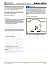
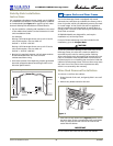
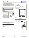
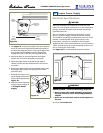
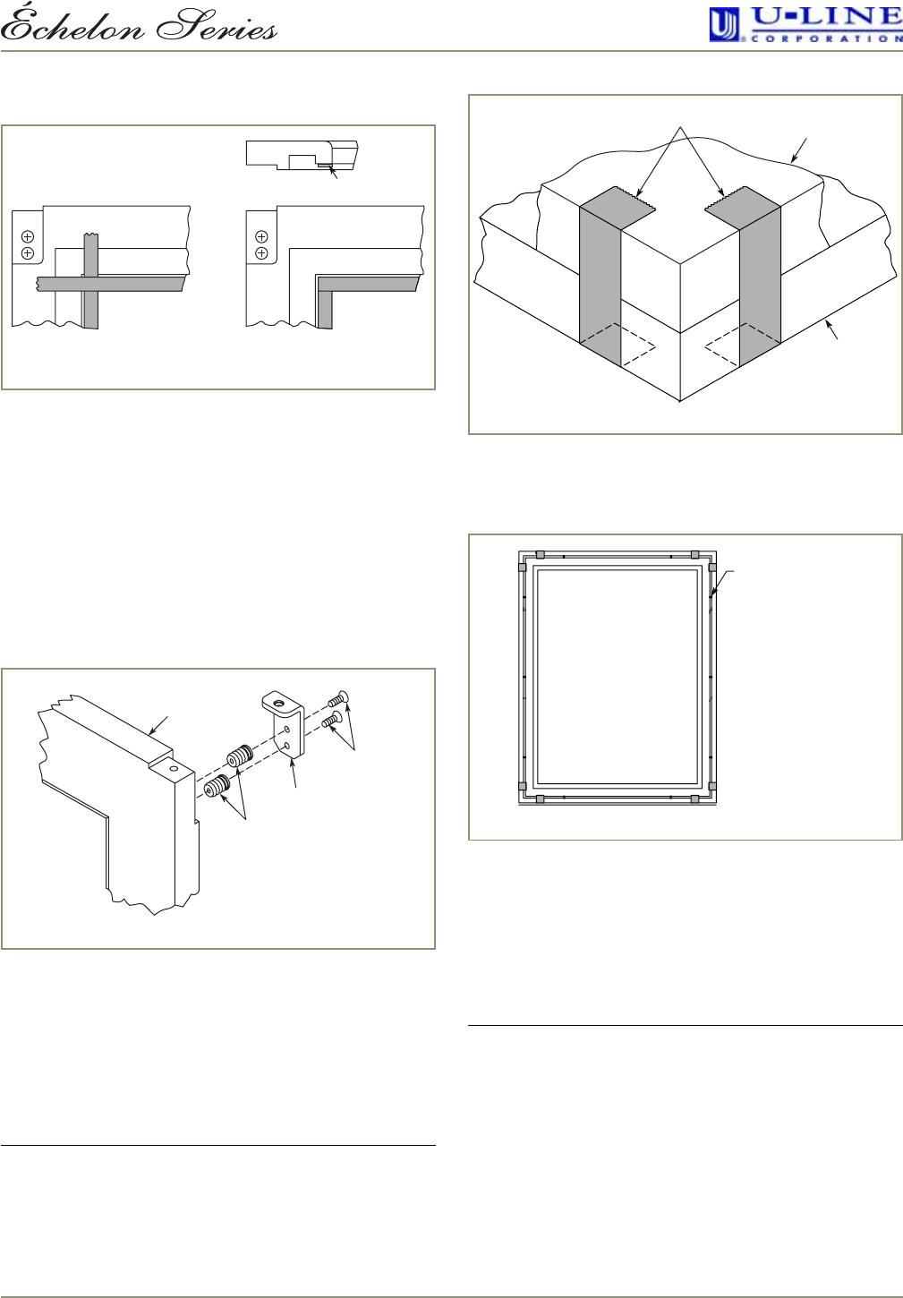
Applying Foam Tape to Overlay Frame (If required)
1. Cut foam tape into four pieces, two pieces the width
of the overlay frame and two pieces the height of the
overlay frame.
2. Remove the adhesive protection strip from one piece of
the foam tape and align to the edge of the overlay
frame as shown in
Figure 18
, adhering the foam tape
to the overlay frame.
3. Trim each piece of tape immediately after application.
Do not allow any overlapping of the foam tape.
Damage to the overlay frame can occur if the foam tape
is not trimmed properly.
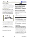
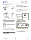
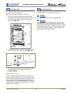
Attaching the Overlay Frame
1. Tap nylon inserts into the top holes drilled in the
overlay frame. Use two #6 screws to attach top pivot
bracket to the overlay frame (see Figure 19).
2. If a user-supplied cabinet handle will be used, attach its
hardware to the overlay frame at this time.
IMPORTANT
User-supplied cabinet handle MUST be counter bored to
make sure mounting hardware is below surface of overlay
frame. Failure to do so can cause damage to overlay
frame and/or door. Overlay frame will not sit flush to door
if mounting hardware is not counter bored.
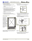
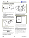
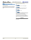
3. Secure the front of the door to the back of the overlay
frame using tape on all four corners, as shown in
Figure 20
. Make sure all four edges are aligned.
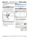
4. Place door and overlay frame on a flat, clean protective
surface. Use the door frame holes as a guide to lightly
punch pilot holes for the #6 x 1" pan-head screws. See
Figure 21
.
5. Attach the door to the overlay frame using the #6 x 1"
wood screws.
IMPORTANT
If you decide to drill pilot holes, remove the door and do
not use a drill bit larger than 7/64". Do not drill deeper
than 3/8". Door frame and overlay frame must be aligned
properly or the door will not operate correctly.
Note: The door frame is designed with a slight amount of
“play” to square it to the overlay frame.
6. Remove all traces of tape securing overlay frame to
door frame.
Incorrect Correct
Inside Edge
Figure 18
Typical Wood
Frame
Top Pivot
Plate
#6 X 5/8"
Flat Head Screw
Two Required
8 mm Plug Insert
Two Required
Figure 19
Door
Frame
Overlay
Frame
Tape
Figure 20
Rear View
of
Door and
Overlay Frame
Punch Pilot Holes
for use
with #
6 x 1" Pan-head
Screws
–
10 Places
Figure 21