


14 2115WC and 2115WCOL, 2175WC and 2175WCOL
To defrost:
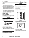
1. Turn unit off.
2. Remove all products from the interior and prop the
door in an open position (2 in. (5 cm) minimum).
3. Allow the frost to completely melt naturally. Clean the
interior and all removed components using a mild non-
abrasive detergent and warm water solution applied
with a soft sponge or non-abrasive cloth.
NOTE:
DO
NOT use any solvent-based or abrasive cleaners. They
will discolor or damage the interior.
4. Dampen a soft sponge or non-abrasive cloth in clean
water and wipe down the cabinet interior and removed
components to remove any detergent residue. Rinse the
sponge or cloth in clean water and repeat as necessary
until the cabinet and components are clean.
5. When the interior is dry, turn unit back on.
Condenser Cleaning
Interval - Every Three Months
To maintain operational efficiency, keep the front grille
free of dust and lint and clean the condenser every three
months. Depending on environmental conditions, more
or less frequent cleaning may be necessary.
WARNING
Disconnect electric power to the unit before
cleaning the condenser.
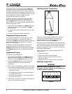
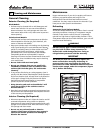
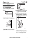
To remove and replace the grille for access to the
condenser fins, follow this procedure:
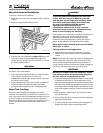
Figure 11
1. Disconnect electrical power to the unit.
2. Loosen two screws
(Figure 11, 1)
completely.
NOTE: Screws are held in the grille by o-ring retainers,
and will not come free of the grille.
3. Remove the grille.
WARNING
DO NOT touch the condenser fins. The condenser
fins are SHARP and can be easily damaged.
CAUTION
DO NOT use any type of cleaner on the condenser
unit.
4. Clean the condenser coil
(Figure 11, 2)
using a soft
brush with a “combing” action or vacuum cleaner. Do
not touch the condenser coil.
5. Position the grille to align the mounting screws with
the holes in the cabinet.
6. Secure, but do not over-tighten both grille screws.
7. Reconnect power to the unit.
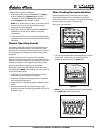
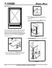
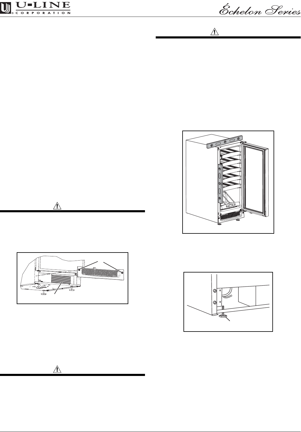
Leveling
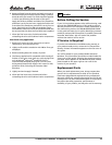
Figure 12
1.
Use a level to check the levelness of the unit from front
to back and from side to side. Level should be placed
along top edge and side edge as shown
(Figure 12)
.
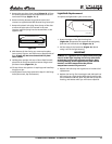
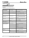
Figure 13
2. If the unit is not level, adjust the feet on the corners of
the unit as necessary
(Figure 13)
.
3. Check the levelness after each adjustment and repeat
the previous steps until the unit is level.
ULIN_0203_A
2
1
ULIN_0206_A
1
ULIN_0044_A