


6
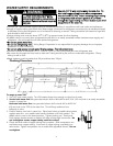
SSeeccuurriinngg tthhee rreeffrriiggeerraattoorrss
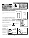
1. Locate and predrill 1/4” (.6 cm) holes in the first
mounting board (supplied). Countersink the bolt
heads into the 2 x 4 board using a 1-1/8” (2.9 cm)
counterbore wood bit 1-1/4” (.6 cm) deep. Locate
and mark 2 wall studs to mount the first 2 x 4 board.
Do not cover the electrical outlet (see “Site
Preparations” on p. 3).
2. Bolt anti-tip mounting board securely to wall studs.
3. Predrill 1/4” (.6 cm) in second mounting board
(supplied). Countersink the bolt heads into the 2x4
board using a 1-1/8” (2.9 cm) counterbore wood bit
1/4” (.6 cm) deep.
4. Attach flush to first 2x4.
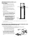
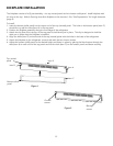
If application does not have studs, mount to the wall
using a minimum of four 1/4” (.6 cm) diameter
fasteners (not supplied). If cabinets are deeper than
24”, mounting board must be shimmed. The shim
must be structurally secured to the mounting
board.
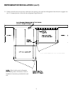
NOTE: THE SPACE BETWEEN THE REAR OF THE
REFRIGERATOR CABINET AND THE
CONDENSING UNIT ASSEMBLY HOUSING
IS 3” (7.6 CM) DEEP. ADDITIONAL
MOUNTING BOARDS MAY BE REQUIRED
IF THE UNIT DOES NOT TOUCH THE
BACK WALL OF THE ENCLOSURE.
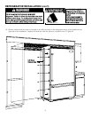
5. To avoid water line damage, verify water line is secure so refrigerator does not run over the water line when
moved into opening.
6. Repeat steps above for second refrigerator.
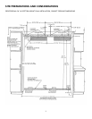
BBeeffoorree mmoovviinngg tthhee rreeffrriiggeerraattoorrss iinn ppllaaccee,, ccoonnffiirrmm tthhee ffiinniisshheedd ddiimmeennssiioonnss,, eelleeccttrriiccaall,, aanndd pplluummbbiinngg llooccaattiioonnss,, mmiinniimmuumm
ddoooorr cclleeaarraanncceess,, aanndd ddoooorr ppaanneell iinnssttaallllaattiioonnss aarree aaccccuurraattee ((sseeee ppaaggeess 22,, 33,, && 44))..
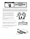
7. Position refrigerators in front of cutout.
8. Remove the top air grille assemblies from both of the refrigerators. (See illustrations on page 7)
a. Remove the center grille blades by lifting up and pulling forward.
b. Remove the grille/end cap assembly by removing the four (4) screws in each black air duct.
c. Remove the black air ducts by removing the
eight (8) screws on the right hinge model and
the seven (7) screws on the left hinge model.
Save the air ducts for the 72” grille installation.
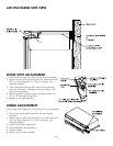
9. Verify operation by plugging power cord. Power
switch will be shipped in the ON position and
showroom switch will be in the ON position. (If
showroom switch is switched to the “OFF” position,
showroom mode is engaged and power is shut off to
the compressor. This mode is for showroom display
only.)
LEVELING
WHEEL BOLTS
LEVELING
FEET
ACCESS TO
LAG BOLTS
2x4 MOUNTING
BOARD
WALL BOARD
OR PLASTER
WALL STUD
LAG BOLT WITH
EXTENDED SHAFT
1-1/2"
24"
O
TE:
E
FRIGERATOR IN A 24"
E
EP OPENING WILL BE
L
USH AT FRONT SURFACE.
S
E 1-1/2" THICK MOUNTING
O
ARD. IF REFRIGERATOR
TO PROTRUDE BEYOND
4
", ADDITIONAL MOUNTING
O
ARD THICKNESS IS
E
QUIRED.
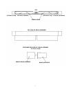
3”
BOARDS
REFRIGERATOR INSTALLATION (con’t)