


MODEL C24EA - ELECTRICAL OPERATION
F25213 (May 2006) Page 42 of 52
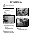
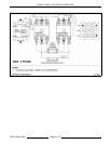
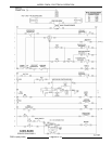
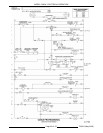
SEQUENCE OF OPERATION
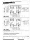
Refer to the correct wiring diagram for model being
serviced when reviewing sequence of operation.
NOTE: If power switch is set to off when service
voltage is applied, steamer will enter the timed drain
cycle.
Basic Model
1. Conditions
A. Steamer connected to correct voltage.
1) 120VAC present across X1 & X2 on
secondary side of main transformer.
B. Steamer connected to water supply with
correct water requirements.
C. Power switch is off (drain handle pulled
out).
1) Time delay relay timed out. Timer has
no output on terminal 1.
D. Condensate thermostat is open.
E. High limit thermostat closed.
F. Pressure switch is closed.
G. Hold thermostat open.
H. Drain open and steam generator tank
(referred to as tank) is empty.
I. Steamer door open.
J. Timer is off.
K. Water level control (WLC) and tank
properly grounded.
2. ON/OFF lever pushed in.
A. Manual linkage closes drain valve and
operates power switch.
1) N.O. contacts close.
B. Amber power light illuminates.
C. X1 potential to L1 of WLC board.
1) 120VAC across L1 & L2 of WLC
board.
2) High level coil (HL) energized on WLC
board. HL LED on WLC board lights.
3. Slow fill solenoid energized through closure of
HL contacts. Tank fills.
4. Water level reaches Low Level Cut-Off (LLCO)
probe.
A. LLCO coil is energized. LLCO LED on
WLC board lights.
B. LLCO N.O. contacts close enabling heating
element circuit.
5. Limiting and regulating contactor coils energize.
Power to heating element. Tank water heats.
6. Water level reaches Low level (L) probe.
A. No action as internal latching relay (ILR-1)
contacts are open.
7. Water level reaches high level (H) probe.
A. Internal latching relay (ILR) coil on WLC
board energizes.
B. High level (HL) coil de-energized by ILR-2
contacts opening.
C. Slow fill solenoid de-energized by opening
of HL contacts on WLC board.
8. Tank water reaches 195E F. Hold thermostat
contacts close.
A. Relay K1 energizes. Timer circuit is
enabled through closure of N.O. contacts
K1-5/3 and K1-6/4.
B. Temperature in tank is maintained at
195E F by hold thermostat control of
regulating contactor through relay contacts
K1-1/5.
9. Timer knob set to time other than zero.
A. Timer motor energized through closure of
N.O. contacts K1-6/4 when time set is
greater than zero. Door switch closure
allows 120VAC across timer wires 18 & 19.
Timer counts down from set time.
B. Tank temperature maintained by control of
regulating contactor coil through N.O.
contacts K1-6/4 and (Timer -1/3, door
switch, K1-5/3).
10. Steamer door is closed.
A. Regulating contactor remains energized as
long as time remains on Timer and door is
closed.
1) Heating element energized
continuously.
11. Temperature of condensate exiting cooking
cavity increases to above 135EF.
A. Condensate thermostat closes energizing
cooling solenoid 1SOL. Condensate is
cooled in drain box before entering facility
drain system.
12. Door opened during timed cook cycle.
A. Timer continues count down until time
equals zero even if steamer door is
opened.
B. Regulating contactor de-energized until
below 195EF.
13. Time reaches zero.
A. Buzzer is energized through N.O. contacts
K1-6/4 and Timer - 1/4.
1) Buzzer remains energized until timer
knob is turned to OFF, new time is set
or drain handle is pulled out (power
switch off).
14. Drain handle pulled out. Tank drains.
A. Power light (1LT-Amber) turns off.