


VHX SERIES STEAMER - ELECTRICAL OPERATION
F25154 (February 2004) Page 24 of 48
ELECTRICAL OPERATION
COMPONENT FUNCTION
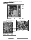
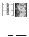
CABINET BASE BOILER CONTROLS
Power Switch ................ Controls 120VAC to the boiler control circuit.
Reset Switch (Manual) ......... Resets the low water level safety circuit on initial startup or the occurrence of
a low water condition. Also, resets the high pressure level safety circuit on
initial startup or the occurrence of a high pressure condition which allows
heating to start.
Boiler Fill Valve ............... Allows water flow to the boiler when energized thru HL-3 contacts on the
water level control.
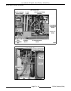
Cold Water Condenser
Valve ....................... Allows cold water to spray thru a nozzle inside the condenser drain box to
condense steam and cool the hot water before discharging into the drain.
Cold Water Condenser
Cycling Thermostat ........... Regulates cold water spray inside the condenser drain box during a cooking
cycle or boiler blowdown/drain.
Cycling Pressure Switch ....... Regulates boiler pressure between cut-out (off) and cut-in (on) pressure
settings of switch.
High Limit Pressure Switch ..... Prevents boiler from reaching pressures above 15 PSI by removing power
from heating circuit. The high limit automatically resets at approximately 12
psi (green ready light on).
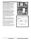
Main Water Level Control ...... A dual function control that allows water to fill and maintain the proper level
in the boiler, providing differential level control; and removes power from
heating circuit if water level drops too low, providing low level cut-off
protection. The control uses three different probe lengths to monitor water
level (high level HL, low level LL, low level cut-off LLCO).
Auxiliary Water Level Control . . . A back up to the low level cut-off on the main water level control. Protects
boiler and heating system components from a low water cut-off condition by
opening the 120VAC voltage path to the heating circuit. The control uses a
single probe to monitor water level (auxiliary low level cut-off Aux LLCO).
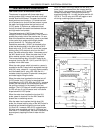
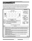
Relay Board .................. Provides a centralized location for wire harness connections and power
transfer thru board relays (K1-K4) to the steamer controls. Also, provides
voltage test points (T1-T7) for verifying voltage to relay coils, N.O. relay
contacts closed, control panel lights and auxiliary contactor coils.
NOTE: The relay’s below are mounted on the relay board and are individually replaceable.
K1 Relay .................... Energized when water level reaches the Aux LLCO probe (water level
condition satisfied).
K2 Relay .................... Energized when high limit pressure switch is closed (high limit pressure
condition satisfied). When K1 & K2 are energized, ready light (green) will be
on.
K3 Relay .................... Energized when K1(2) N.O. contacts close and reset switch is activated.
When K3 is energized, K3(2) N.O. contacts close and low water light turns
off.
K4 Relay .................... Energized when K2(2) N.O. contacts are closed and reset switch is
activated. When K4 is energized, K4(2) N.O. contacts close and high
pressure light turns off. When K3 and K4 are energized, power is supplied to
auxiliary contactors A & C.