


VHX SERIES STEAMERS - REMOVAL AND REPLACEMENT OF PARTS
F25154 (February 2004)Page 9 of 48
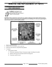
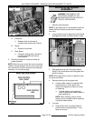
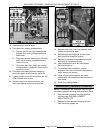
LEFT SIDE VIEW SHOWN
4. To remove:
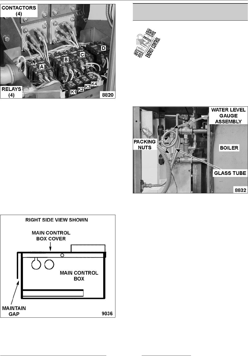
A. Contactors.
1) Release catch at the base of
contactor and remove from DIN rail.
B. Relays.
1) Remove from socket.
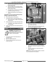
C. Relay Board.
1) Compress locking tab on the board
mounting standoffs and remove
control board.
5. Reverse procedure to install and check for
proper operation.
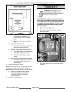
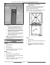
NOTE:
When the main control box cover is properly
installed, the gap between the front lip of cover and
main control box must be maintained for adequate
ventilation. Do not seal the gap.
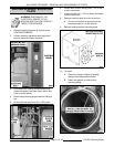
WATER LEVEL GAUGE
ASSEMBLY
WARNING: DISCONNECT THE
ELECTRICAL POWER TO THE
MACHINE AND FOLLOW LOCKOUT /
TAGOUT PROCEDURES.
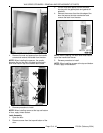
1. Remove right side panel.
NOTE: If right side panel is not accessible, open the
cabinet door and remove control panel to access
from front.
2. Loosen packing nuts on glass tube until threads
disengage then slide nut toward center of tube.
3. Slide glass tube up until it clears the bottom
fitting, tilt out at the bottom and slide glass tube
down to remove.
NOTE: Clean glass tube if cloudy or replace if chips
or cracks are noticed.
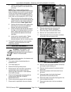
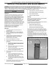
4. Remove packing nuts from glass tube.
A. A single rubber washer is installed inside
each packing nut. Clean debris from
washer and inspect the rubber for cracks
or hardening.
1) If rubber washer needs replacing,
install a replacement rubber washer in
each packing nut.
NOTE: When installing, ensure friction
washer (flat) is installed inside the packing
nut before rubber washer.
5. To Install:
A. Slide packing nuts onto glass tube and
position each nut approximately 1" from
open end on tube.