


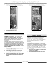
ELECTRIC COMBI OVEN - REMOVAL AND REPLACEMENT OF PARTS
Page 15 of 68
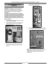
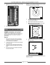
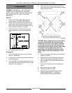
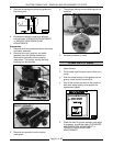
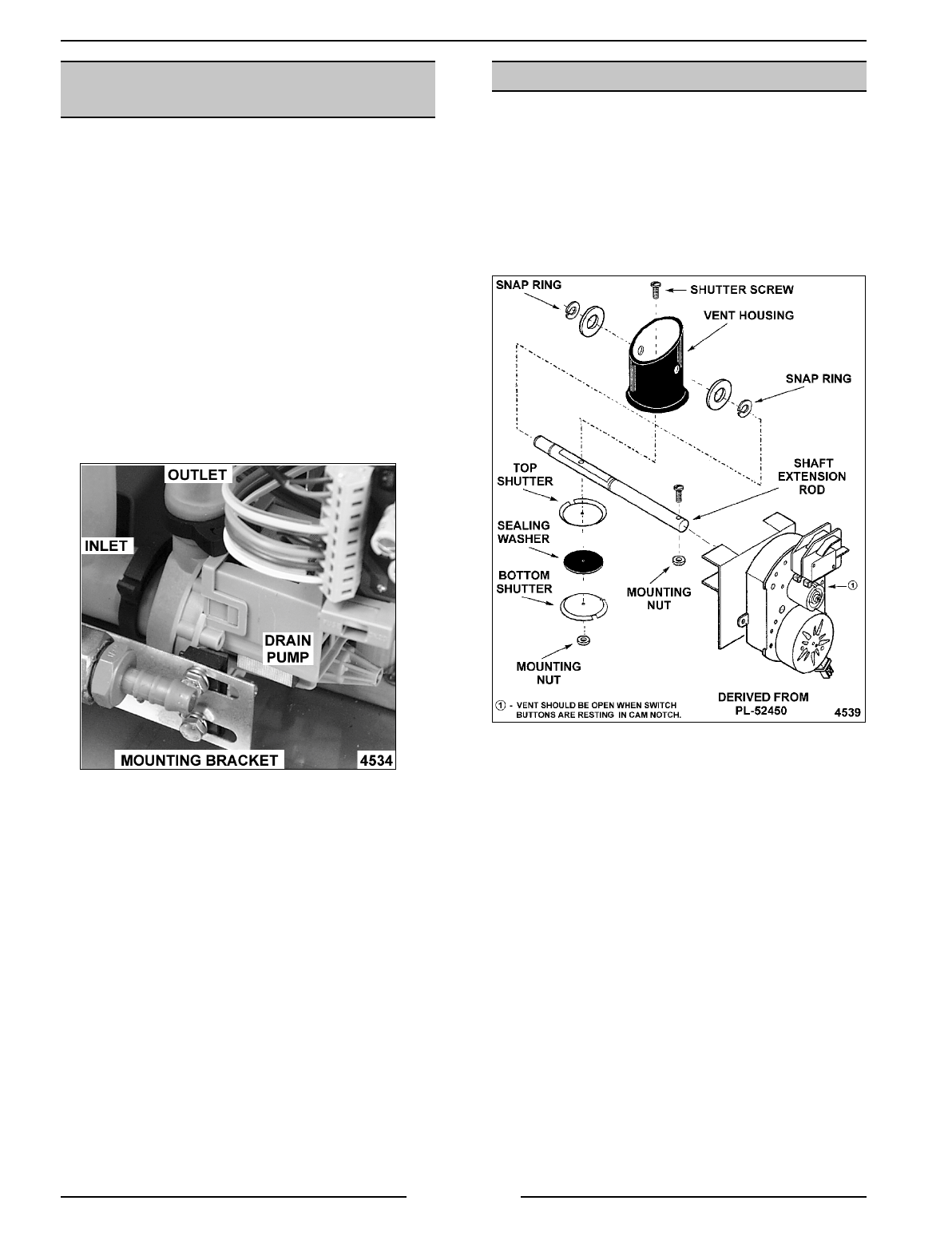
VENT DAMPER ASSEMBLY DIAGRAM
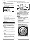
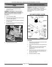
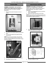
STEAM GENERATOR DRAIN
PUMP
1. Turn off the oven and allow the steam
generator to drain.
WARNING:
DISCONNECT THE ELECTRICAL
POWER TO THE MACHINE AT THE MAIN
CIRCUIT BOX. PLACE A TAG ON THE CIRCUIT
BOX INDICATING THE CIRCUIT IS BEING
SERVICED.
2. Turn off the water supply.
3. Remove the right side panel as outlined under
“COVERS AND PANELS”.
4. Disconnect lead wires and hoses connected to
the drain pump.
5. Remove the bolts from the mounting bracket
that secure the pump.
6. Reverse procedure to install.
VENT DAMPER ASSEMBLY
WARNING:
DISCONNECT THE ELECTRICAL
POWER TO THE MACHINE AT THE MAIN
CIRCUIT BOX. PLACE A TAG ON THE CIRCUIT
BOX INDICATING THE CIRCUIT IS BEING
SERVICED.
Vent Motor
1. Remove the right side panel as outlined under
“COVERS AND PANELS”.
2. Disconnect the lead wires from the switch and
motor.
3. Remove the screw and nut behind the motor
assembly that connects motor to shaft
extension rod.
4. Remove the motor and switch assembly from
the oven by sliding the mounting bracket out
from the oven frame.
5. Reverse procedure to install.