


ELECTRIC COMBI OVEN - REMOVAL AND REPLACEMENT OF PARTS
Page 22 of 68
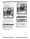
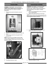
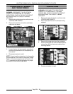
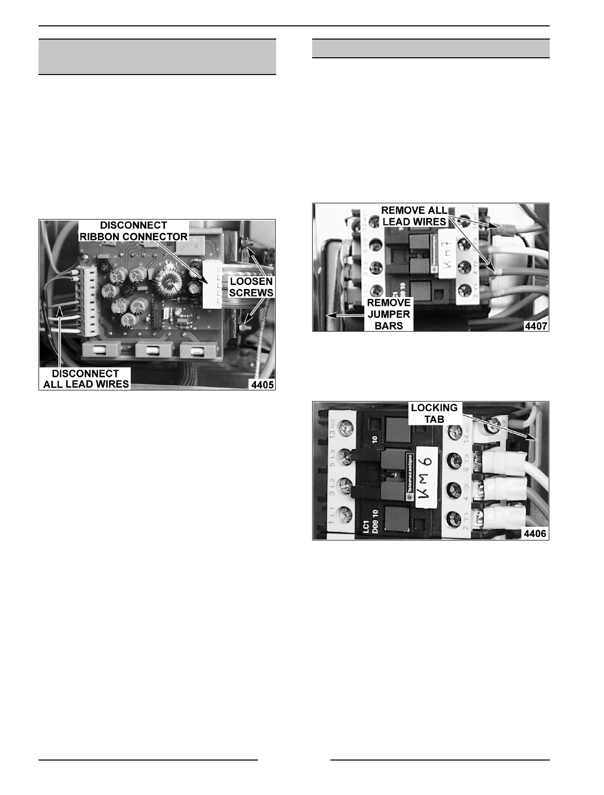
POWER SUPPLY BOARD
AND TRANSFORMER
WARNING:
DISCONNECT THE ELECTRICAL
POWER TO THE MACHINE AT THE MAIN
CIRCUIT BOX. PLACE A TAG ON THE CIRCUIT
BOX INDICATING THE CIRCUIT IS BEING
SERVICED.
1. Remove the right side panel as outlined under
“COVERS AND PANELS”.
2. Disconnect lead wire connections and ribbon
cable from the board.
3. Loosen the two nuts securing the assembly to
the mounting bracket and lift the assembly off
the bracket.
4. Reverse procedure to install.
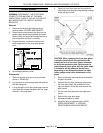
NOTE
: Ensure transformer tap wire is in the position
that corresponds to the machine data plate voltage.
Refer to the “power supply board and transformer
(1T) “ component on the wiring diagram for proper
connection of the individual lead wires.
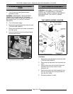
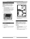
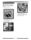
CONTACTORS
WARNING:
DISCONNECT THE ELECTRICAL
POWER TO THE MACHINE AT THE MAIN
CIRCUIT BOX. PLACE A TAG ON THE CIRCUIT
BOX INDICATING THE CIRCUIT IS BEING
SERVICED.
1. Remove the right side panel as outlined under
“COVERS AND PANELS”.
2. Disconnect lead wires for the contactor being
replaced.
3. Remove the jumper bars from the contactors.
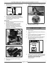
4. Pull the locking tab out at the contactor base to
release the catch and remove contactor from
mounting bracket.
5. Reverse procedure to install.