


5
NOTE:
Before performing any type of installation, cleaning, or
removing a light bulb, turn the control, (Thermostat, Refrigerator
or Freezer Control depending on the model) to OFF and then
disconnect the refrigerator from the electrical source. When you
are finished, reconnect the refrigerator to the electrical source
and reset the control (Thermostat, Refrigerator or Freezer Control
depending on the model) to the desired setting.
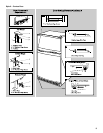
Water Supply Connection
(on some models)
Read all directions carefully before you begin.
IMPORTANT:
■
If operating the refrigerator before installing the water
connection, turn ice maker to the OFF position to prevent
operation without water.
■
All installations must be in accordance with local plumbing
code requirements.
■
Use copper tubing and check for leaks. Install copper tubing
only in areas where temperatures will remain above freezing.
■
It may take up to 24 hours for your ice maker to begin
producing ice.
Tools required:
Standard screwdriver,
⁷⁄₁₆
in. and
¹⁄₂
in. open-end
wrenches or two adjustable wrenches,
¹⁄₄
in. nut driver,
¹⁄₄
in. drill
bit, hand drill or electric drill (properly grounded).
NOTE:
Your refrigerator dealer has a kit available with a
¹⁄₄
in. (6.35 mm) saddle-type shut-off valve, a union, and copper
tubing. Before purchasing, make sure a saddle-type valve
complies with your local plumbing codes. Do not use a piercing-
type or
³⁄₁₆
in. (4.76 mm) saddle valve which reduces water flow
and clogs more easily.
Cold Water Supply
The ice maker water valve contains a flow washer which is used
as a water pressure regulator. The ice maker needs to be
connected to a cold water line with water pressure between 30
and 120 psi. If a problem occurs, call your utility company.
Connecting to water line:
1.
Unplug refrigerator or disconnect power.
2.
Turn OFF main water supply. Turn ON nearest faucet long
enough to clear line of water.
3.
Find a
¹⁄₂
in. (1.3 cm) to 1
¹⁄₄
in. (3.18 cm) vertical COLD water
pipe near the refrigerator.
NOTE:
Horizontal pipe will work, but the following procedure
must be followed: Drill on the top side of the pipe, not the
bottom. This will help keep water away from the drill. This
also keeps normal sediment from collecting in the valve.
4.
To determine the length of copper tubing you will need,
measure from connection on lower left rear of refrigerator to
water pipe. Add 7 ft (2.1 m) to allow for moving refrigerator for
cleaning. Use
¹⁄₄
in. (6.35 mm) O.D. (outside diameter) copper
tubing. Be sure both ends of copper tubing are cut square.
5.
Using a grounded drill, drill a
¹⁄₄
in. (6.35 mm) hole in the cold
water pipe you have selected.
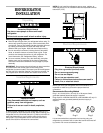
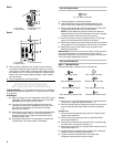
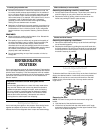
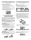
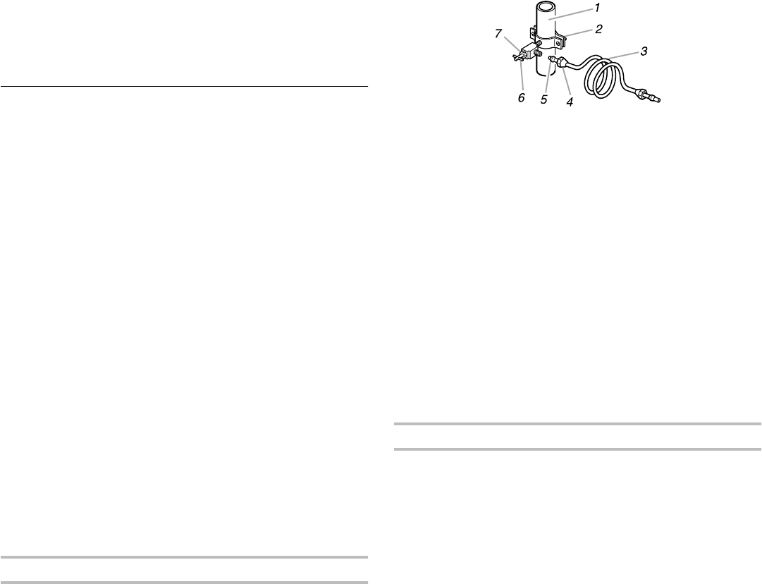
1. Cold Water Pipe 5. Compression Sleeve
2. Pipe Clamp 6. Shut-Off Valve
3. Copper Tubing 7. Packing Nut
4. Compression Nut
6.
Fasten shut-off valve to cold water pipe with pipe clamp. Be
sure outlet end is solidly in the
¹⁄₄
in. (6.35 mm) drilled hole in
the water pipe and that washer is under the pipe clamp.
Tighten packing nut. Tighten the pipe clamp screws carefully
and evenly so washer makes a watertight seal. Do not
overtighten or you may crush the copper tubing, especially if
soft (coiled) copper tubing is used. Now you are ready to
connect the copper tubing.
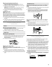
7.
Slip compression sleeve and compression nut on copper
tubing as shown. Insert end of tubing into outlet end squarely
as far as it will go. Screw compression nut onto outlet end
with adjustable wrench. Do not overtighten.
8.
Place the free end of the tubing into a container or sink, and
turn ON main water supply and flush out tubing until water is
clear. Turn OFF shut-off valve on the water pipe. Coil copper
tubing.
Connecting to refrigerator:
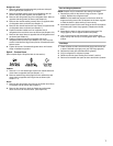
NOTE:
The first step for connecting the water line to your
refrigerator is different depending on the type of water valve
provided with your refrigerator. See the diagrams below to
determine the style of valve you have. (On kit models, assemble
water valve to refrigerator per kit instructions.)
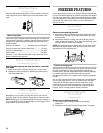
1.
For Style 1
,
disconnect the tube clamp on the back of the
product and insert the copper tubing through the clamp, as
shown. Remove the tape label from the valve inlet and insert
copper tubing until it bottoms out (approximately
³⁄₄
in. [1.9
cm]). Tighten nut by hand as much as possible; then turn the
nut an additional
¹⁄₂
turn using a wrench. Do not overtighten.
Re-attach the tube clamp and tube to the back of the cabinet.
Skip to Step 2.
For Style 2
,
disconnect the tube clamp on the back of the
product and insert copper tubing through the clamp as
shown. Attach the copper tube to the valve inlet using a
compression nut and sleeve as shown. Tighten the
compression nut. Do not overtighten. Re-attach the tube
clamp and tube to the back of the cabinet. Move to Step 2.
2.
Turn shut-off valve ON. Check For Leaks.
Tighten any
connections (including connections at the valve) or nuts that
leak.