


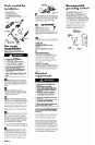
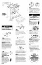

Tools needed for
installation:
l
hand or electric drill
concrete/ceramic floors: Q/16” masonry drill bit
wood floors: 3/32” drill bit
l
gas line shutoff valve
l
L.P.-resistant pipe-joint compound
l
A.G.A. design-certified flexible metal connector
(A-5 feet)
c
wrench V
‘V
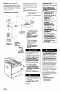
Gas supply
requirements
Observe all governing codes and
ordinances.
Fire Hazard
l
Range must be connected to a
regulated gas supply.
. L.P. gas supply must Not exceed a
pressure of 14-inch water column. This
must be checked by a qualified
technician before installing this range.
l
Do Not use an open flame to test for
leaks from gas connections.
l
New, A.G.A. design-certified flexible
gas line should be used when local
codes permit.
Failure to follow these instructions could
result in a fire, explosion or personal
injury.
A
n
This installation must conform with
local codes and ordinances. In the absence
of local codes, installations must conform
with American National Standard, National
Fuel Gas Code, ANSI 2223.1 - latest
edition**.
B
n
Input ratinas shown on the
serial/rating plate are for elevations up to
2,000 feet. For elevations above 2,000 feet,
ratings are reduced at a rate of 4% for each
1,000 feet above sea level.
C
n
This range is equipped for use with
NATURAL gas It is design-certified by A.G.A.
for NATURAL and L.P. gases with appropriate
conversion. The serial/rating plate, located
under the maintop, has information on the
type of gas that can be used. If this
information does not agree with the type of
gas available, check with the local gas
supplier. See Panel E for L.P. gas conversion
instructions.
D
n
Provide a gas supply line of 3/4” rigid
pipe to the range location. A smaller size -
pipe on long runs may result in insufficient
gas supply. Pipe-joint compounds made for
use with L.P. gas must be used. With L.P. gas,
piping or tubing size can be l/2” minimum.
L.P. gas suppliers usually determine the size
and materials used on the system.
E
n
If local codes permit, a new, A.G.A.
design-certified, 4-5 foot long, l/2” or 314”
I.D., flexible metal appliance connector is
recommended for connecting this range to
the gas supply line. Do Not kink or damage
the flexible tubing when moving the range.
A l/2” male pipe thread is needed for
connection to pressure regulator female
pipe threads.
shutoff valve
I
r
n
The supply line shall be equipped with
an approved shutoff valve. This valve should
be located in the same room as the range
and should be in a location that allows ease
of opening and closing. Do Not block
access to shutoff valve.
supply
line, a corn
pipe fittings must
obtain an in-line
range. All strains must be removed from the
supply and fuel lines so range will be level
and in line.
H
n
The inlet pressure to the regulator
should be as follows for both operation and
checking regulator setting:
NATURAL GAS:
Set pressure 5 inches
Maximum inlet pressure 14 inches
L.P. GAS:
Set pressure 11 inches
Maximum inlet pressure 14 inches
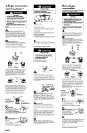
I W Line pressure testing:
Testing above l/2 psi (gauge)
The range and its individual shutoff valve
must be disconnected from the gas supply
piping system by closing its individual
manual shutoff valve during any pressure
testing of the gas supply piping system at
test pressures equal to or greater than l/2
psig (3.5 kPa).
Testing at l/2 psi (gauge)
The range must be isolated from the gas
supply piping system by closing its individual
manual shutoff valve during any pressure
testing of the gas supply piping system at
test pressures equal to or less than l/2 psig
(3.5 kPa).
Electrical
requirements
Electrical Shock Hazard
l
Electrical ground is required on this
appliance.
l
Do Not ground to a gas pipe.
l
Do Not modify the power supply cord
plug. If it does not fit the outlet, have a
proper outlet installed by a qualified
electrician.
l
Do Not have a fuse in the neutral or
grounding circuit. A fuse in the neutral
or grounding circuit could result in
electrical shock.
l
Do Not use an extension cord with this
appliance.
l
Check with a qualified electrician if you
are in doubt as to whether the
appliance is properly grounded.
Failure to follow these instructions could
result in serious injury or death.
If codes permit and a separate grounding wire
is used, it is recommended that a qualified
electrician determine that the grounding path
is adequate.
A 120-volt, 60-Hz, AC-only, 15.ampere, fused
electrical supply is required. A time-delay
fuse or circuit breaker is recommended. It is
recommended that a separate circuit
serving only this appliance be provided.
Electronic ignition systems operate within
wide voltage limits, but proper grounding
and polarity are necessary. In addition to
checking that the outlet provides 120-volt
power and is correctly grounded, the outlet
must be checked by a qualified electrician
to see if it is wired with correct polarity
A wiring diagram is included in the literature
package. The wiring diagram is also located
on the underside of the storage drawer.
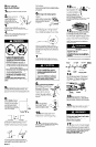
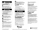
Recommended
grounding method
For your personal safety, this appliance must
be grounded. This appliance is
manufactured with a power supply cord
having a 3-prong grounding plug. To
minimize possible shock hazard, the cord
must be plugged into a mating, 3-prong,
grounding-type, wall receptacle, grounded
in accordance with the National Electrical
Code, ANSVNFPA 70 - latest edition*, and
all local codes and ordinances. (See Figure
1.) If a mating wall receptacle is not
available, it is the personal responsibility and
obligation of the customer to have a
properly grounded, 3-prong, wall receptacle
installed by a qualified electrician.
J-prong
grounding-type
wall receptacle
J-prong
grounding
plug
power
/
supply cord
Figure 1
Panel B