


the line drawn.
Note: If there is a cabinet on only one side,
the anti-tip bracket must be installed against
the cabinet,
Go to Step 7.
Now start...
With range in kitchen.
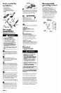
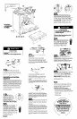
1
w Remove racks and other parts from
inside oven.
2
W Place one foot on
the shipping base. Tilt
range forward slightly to
free rear legs. Gently
lower range to floor. Tilt
range backwards until legs
are free.
3
w Remove shipping
materials, tape and protective film from
range. Do Not
remove cardboard shipping
base at this time.
& n
Check
that the rear leveling
leg is engaged in the
anti-tip bracket. (For
no-cabinet installations,
check that both rear
legs are engaged in anti-
tip brackets.) If a leveling
leg is not properly engaged,
remove and reposition the bracket to insure
that the leveling leg fits properly in the
bracket.
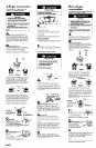
6
A
n
If range is Not installed against a
cabinet,
both anti-tip brackets must be
installed.
l
Slide range into final location.
Mark a line on the floor along
sides of range about one-half
the distance from the rear
to the front.
-;iI
13
w Place rack in oven. Place level
lineA-
l
Mark floor to show where the center of the
rear leveling legs are on the right and left
sides of range. Slide range out of location.
Draw a straight line between the two marks.
4
W Lower leveling legs approximately l/4
on rack, first side to side; then front to back.
If the range is not level, pull the range
forward until rear leveling leg is removed
from the bracket. Adjust the legs up or down
until range is level. Push range back into
position. Check that the rear leveling leg is
engaged in the bracket.
Note: Oven must be level for satisfactory
baking conditions.
inch or to a point where the range base
does not touch the floor.
l
Place an anti-tip bracket on the floor.
Align the bracket with the lines for the right
rear leveling leg and the line drawn for the
right side of the range as shown. Repeat for
the left side of range using the other anti-tip
bracket.
Go to Step 7.
Personal Injury Hazard
Fire Hazard
Do Not make connection too tight. The
regulator is die cast.
Overtightening may crack the regulator,
resulting in a gas leak and possible fire or
explosion.
7
l
To reduce the risk of tipping of the
appliance, the appliance must be
secured by properly installed floor
mounted anti-tip bracket(s) supplied
with the range.
l
Save these installation instructions. If
range is moved to a new location, the
anti-tip bracket(s) must be removed and
reinstalled in the new location.
Electrical Shock Hazard
l
Take special care when drilling holes
into
the floor. Electrical wires or plumbing
may be located beneath floor.
l
Locate the electrical circuits that could
be affected by the installation of the
bracket(s) and turn off power to these
circuits.
Failure to follow these instructions may
result in electrical shock or other personal
injury.
1
n
Use a pencil to mark the two
mounting screw hole locations on anti-tip
bracket(s). Remove bracket(s) from position
All connections must be wrench-tightened.
JW’d’,“t’e2”
l/2”
nipple
l/2” union
pressure
w 1 J
T-T- “p
3/A”
manual
l/2” nipple
nipple
shutoff
maximum length
14
valve
21-l/2”
w Assemble the flexible connector
Property Damage/Floor Damage
l
Contact a qualified floor covering
installer for the best procedure to drill
mounting holes through your type of
floor covering.
l
Before moving range across floor, slide
range onto cardboard or hardboard.
Failure to follow these instructions may
result in damage to floor covering.
from the gas supply pipe to the pressure
regulator in this order: 3/4” nipple, 3/4” to
l/2” reducer, l/2” nipple, manual shutoff
valve, l/2” nipple, union, l/2” nipple.
L
8
n
To mount anti-tip bracket(s)
to wood floor,
drill a 3/32” hole at
each mounting screw location.
To mount anti-tip
bracket(s) to concrete or
ceramic floor,
use a
cabts!
masonry drill bit to drill 3/ 16”
holes at each mounting screw
location. Tap plastic anchors
into mounting holes in floor with
hammer.
3
n
If installing the range in a mobile home,
you MUST secure the range to the floor. Any
method of securing the range is adequate as
long as it conforms to the standards listed in the
Mobile home installation instructions, Panel A.
Tflexible
connector
regulator
15
w Use pipe-joint compound
6
n
If ranae will be installed
resistant to the &&ion of L.P. g&s to seal all
gas connections. If flexible connectors are
used, be certain connectors are not kinked.
with a cabinet on one or
both sides,
one anti-tip
bracket must be installed,
l
Measure the distance
from the center of the
leveling leg to the furthest
point that extends from the
back of the range.
9
W Line up holes in
anti-tip bracket(s) with
holes in floor. Use the
screws provided to fasten
anti-tip bracket(s) to floor
16
W Open the shutoff valve in the aas
supply line. tiait a few minutes for gas to -
move through the gas line.
I
1
61
leveling*+j k
leg
10
w Move ranae close to final
position. Remove thevcardboard or
hardboard from under the range. Plug
power supply cord into the grounded outlet.
Fire Hazard
Do Not use an open flame to test for leaks
from gas connections.
Checking for leaks with a flame may
result in a fire or explosion.
17
w Use a brush and liquid detergent
to test all gas connections for leaks. Bubbles
around connections will indicate a leak. If a
leak appears, shut off gas valve controls and
adjust connections. Then check connections
again.
NEVER TEST FOR GAS LEAKS WITH A
MATCH OR OTHER FLAME.
Clean all
detergent solution from range.
l
Mark the distance measured in Step 6 from
the rear of the cabinet opening or wall at
the location where the range will be
installed. Additional space may be needed
for gas line located behind the range,
11
n
Carefully move range to final
position. Remove storage draw& by pulling
out and lifting up. Set the drawer on a
protected surface.
l
Place one end of the anti-tip bracket on
the floor against the cabinet side so that the
inside edge of the bracket is aligned with
Panel C