


See cooktop
Cabinet
di
Cutout width:
30” vent-27-l/2”
manufacturer’s
instructions for
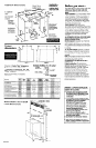
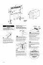
Before you start...
Important: Observe all governing codes and
ordinances. Failure to meet codes and
ordinances could lead to fire or electrical
shock.
Proper installation is your responsibility. Make
sure you have everything necessary for
correct installation. It is the responsibility of
the installer to comply with the installation
clearances specified on the model/serial
rating plate. The model/serial rating plate is
located on the front of the downdraft vent
above the wiring box cover.
Check location where retractable
downdraft vent will be installed. The location
should be away from strong draft areas, such
as windows, doors and strong heating vents
or fans. Before making countertop cutout,
check that retractable downdraft vent and
cooktop location will clear cabinet walls,
backsplash, and rear wall studs inside
cabinet.
ALL OPENINGS IN THE WALL OR FLOOR WHERE
RETRACTABLE DOWNDRAFT VENT IS TO BE
INSTALLED MUST BE SEALED.
Electrical ground is required. See “Electrical
requirements, I Panel B.
When installing retractable downdraft vent,
the cabinet drawer will need to be removed
and the drawer front installed permanently
to cabinet.
30” min. base cabinet is required. If cabinet
has a drawer, 3-l/2” depth clearance from
the countertop to the top of the drawer (or
other obstruction in the base cabinet) is
required.
Note: Retractable downdraft vent is installed
directly behind the cooktop. Install
retractable downdraft vent first.
This appliance is not approved for use in
mobile homes.
Cabinet construction: This appliance is
designed for use in a cabinet with a depth of
24 inches. The maximum depth of the
overhead cabinet is 13 inches. Overhead
cabinets installed at either side of the
appliance must be 18 inches above the
cooking surface. See cooktop Installation
Instructions for the minimum distance
between the front edge of the countertop
and front edge of cooktop. The minimum
horizontal distance between the overhead
cabinets is the same as the width of the
installed appliance.
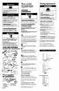
A = cabinet wall
to rear line of
A
cutout
Allow l/2” from
L
rear of downdraft
vent to back wall
T
of cabinet.
Left cabinet
wall cutout:
Centerline is
17-3/16” from
countertop.
\
rear edge of
cooktop overlaps
edge of downdraft
vent by J/8”.
Use dimensions
\
for ductwork
cutout location
that applies to
your installation.
Locate power
supply junction
box at lower right
corner of cabinet.
cutout
l-
x---d
dimensions JF)j
Jt
-i+
C
Figure 1
Figure 2
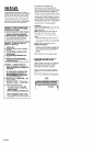
Dimension A: If just a “Max.” dimension is
given, that dimension must be used.
*If dimension A is between the “Min.” and
“Max.“: Subtract actual dimension “A” from
‘A Max. y Divide by 2.
Example: RC8536, 19- l/2” cutout
“A Max.”
20-l /4”
Actual “A” - 19-l/2”
314” + 2 = 318
B (for A Max.) 2-l/2”
Add to ‘B (for A Max.)” for required
B dimension.
+ 3ian
2-7/8”
= Required B
dimension
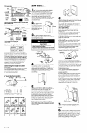
Models
C8200XY/RC8400XY/
k84ooXYQ
[i#ii$$&iijiiiFj
::.::::$g.fg::::::::::::: I
:~~ 19-l 14” ~~~
. . . . . . . . . . . . . . . . . . . . . . . . . . . . . . . . . . . . . . . .
p-5/8”
.,...,
i.ifiii~~~~~~~iiiiil: 27-,/p”
. . . . . . . . . ..~.......... . . . . . . . . .
. . . . . . . . . . . . . . . . . . . . . . . . . . .
. . . . . . . . . . . . . . . . . . . . . . . . . . .
,........................ . . . . . . . . . . . . . . .
:3~::;wj:~::::::::::::::::::::::::: :::::::::::::::::~:~:::::~:~:~:~:~:
RC8536XT *
:,:.: :.. .ii..
i::ii::~:i:jiiiij 1
:j:j:~ . . . . ..~........
li;i;i;i;i;i;i;i::;i;i;i;j;i;i;i;i;:
;..:
,:::::Jz@ “. n..
:.:.:.;: . . . . :::&gg$ 20- 1 /4”
iiiiiiiiaiis~~~
::::::::, %:; ,:
: . . . . . . . . . . . . . . .
2 - 1 / 2 ”
. . . . . . . . . _.,.,., ,...,.
i:::::::~:::::~:~:~:~:~:~:~:~:~:~:~
33- , ,2”
RC8600XXB/Q
:iii:!! 1
::::::::::::::::::::::::::::::::::::::::::
.:,:,~~:.:.~:,~:,::::::::::j:j:j:j:j:j:~:~~:
.A.. . . . :....... . . . . . . . . . .
iiijiiijiiijjiijijijjijijjijiiijijjjjjij~
PO- 1 /4” iiiliiilililiiiiililii:i:i;:i:i:l:i:i:l:~:~~~~
. .A.. . . . . . . . . . . . . . . . ,.,..,,,,,..,,..,,.,.
2- 118”
~ii~: 27-11~
. . . . . . . . . . . . . . . . . . . . . . . . . . . . . . . . .
........ .
RC8436XT/RC8436XTW * +ziiis
. . . . . . . . . . . . . . .
8’.-“‘“”
.........
.iiiBig3: ,,., .“,&
..~.,.,.,.,.~..~.~.,. &3? 20-5/8”
~~~P~~~ 2-5/1(fy
..........
~ 33-l/2”
..:::.
RC8330XTB/RC8430XT/ ::.:.: ..,
. . . . . . . . . . . . . . . . . . . . . . . ,...,...........
.:.:.:.:i
x:;:;:::.:.:.:.:
,...... J@$i’i’i’
. . . . . . . . . . . . . . . . . . . . . .::.... ,....
] RC8430XTW
l
. . . . :.:.:.:.:
1
:::::. .,:,. ..:.. .~.
.>:.:: .,.,.,.,. :.:.:.:,:.:.:.
:.i~~~~~~~~~
$4 ..::i:i:
2&5,8”
~~~~~
:i:i:i:i:i:i:i:i:~:i:i:i:i:i:i:i:i:i
2-5/l 6”
~ 27-1,2~~
. .,..
3i:~:~:~~~~~~~~~~~~~~~~~:~:~~~:~:~~~:~~:~~~~::
,...... .,.,.
SC8630EX and EAW/N/B/Q s
. . . . . . . . . . . . . . . . . ,.:
@:jZ
2
.:.:.:.: . . . . . . . . . . . . . . . . . . . . . . . . . . . . . . . . .
:,:.:.:.:::::::::::::::::j::::::::::::::::
:.: . . . . . . . . . . . . . . . . . . . .::: . . . . . .
., . . . . . . . . . . . . . . . . . . . . . . . . . . . ,...,. . . . .
. . . . . . . . . . . . . . . . . . . . . . . . .
,............. :::::::
, Q’ ~~~~~~~~~~~
:.:.>>>>: .,.,...,.,.,.,.,.,.,.,.,. >:.:.:.:
l-314”
iiidi%d~~Sjiii:l 27- l/y
SC8430ERbC8430ERH ;iiiip
SC8536EX/SC8536EXH/
SC&36EXB/SC8536EXQ
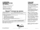
WARNING - TO REDUCE THE RISK OF FIRE,
ELECTRIC SHOCK, OR INJURY TO PERSONS,
OBSERVE THE FOLLOWING:
A. Installation Work And Electrical Wiring
Must Be Done By Qualified Person(s) In
Accordance With All Applicable Codes
And Standards, Including Fire-Rated
Construction.
B. The combustion airflow needed for safe
operation of fuel-burning equipment may
be affected by this unit’s operation.
Follow the heating equipment
manufacturer’s guideline and safety
standards such as those published by the
National Fire Protection Association
(NFPA), and the American Society for
Heating, Refrigeration and Air
Conditioning Engineers (ASHRAE), and
the local code authorities.
C. When cutting or drilling into wall or
ceiling, do not damage electrical wiring
and other hidden utilities.
D. Ducted fans must always be vented to
the outdoors.
E. If this unit is to be installed over a tub or
shower, it must be marked as appropriate
for the application.
Retractable downdraft
30” vent width - 26-518”
36” vent width - 32-518”
vent dimensions
114”
tractable
mt height
-2-l/8”
I
3O’vent base width - 27”
36” vent base width - 3T
26
:
Panel A