


Fire Hazard
Do Not obstruct the flow of combustion
and ventilation air.
Failure to follow this instruction could
result in fire.
Injury Hazard
To eliminate the risk of burns or fire, avoid
installing cabinet storage above the
cooking surface. If cabinets are already
installed, avoid the use of cabinets while
cooktop is in use.
Reaching over a heated cooking surface
could result in a serious burn.
Use two or more people to move and
install downdraft vent.
Failure to follow these instructions can
result in back or other injury.
It is the customer’s responsibility:
To contact a qualified electrical installer.
To assure that electrical installation is
adequate and in conformance with National
Electrical Code, ANSRNFPA 70 - latest
edition’, and local codes and ordinances.
Electrical Shock Hazard
Take special care when drilling holes into
the wall for venting or electrical wiring.
Electrical wires may be concealed behind
the wall covering.
Do Not use this downdraft vent with any
solid state fan speed control device.
Failure to follow these instructions can
result in death. fire or electrical shock.
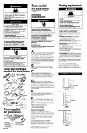
Tools and materials
needed for installation:
8mm or
3/a'!
nut
driver or cable
ratchet
’ ’ orkevholesaw
Phillips fl
screwdriver
screwdriver
@
‘I
L
safety glasses
Parts supplied v
for installation:
l
2 end caps
l
1 bag of fasteners
l
2 lower support legs
l
I metal cover
l
2 overcounter
l
1 backdraft damper
mounting brackets
l
literature package
l
2 undercounter
mounting brackets
Panel B
Parts needed
for installation:
l
2 conduit connectors
l
ductwork
l
1 wall cap
Electrical
requfrements
I
a4
rcc
Electrically ground downdraft vent.
/ . Electrical. Shock Hazard
Failure to follow this mstructron could
result in death, fire or electrical shock.
If codes permit and a separqte grounding
wire is used, it is recommended that a
qualified electrician determine that the
grounding path is adequate.
Do Not ground to a gas pipe.
Check with a qualified electrician if you are
not sure the downdraft vent is properly
grounded.
Do Not have a fuse in the neutral or
grounding circuit.
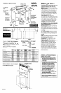
IMPORTANT: Save lnstallcrtion Instructions for
electrical inspector’s use.
A
w A 120-volt, 60-Hz, AC-only electrical
supply is required on a separate 15ampere
circuit, fused on both sides of the line. A
time-delay fuse or circuit breaker is
recommended. The fuse must be sized per
local codes in accordance with the
electrical rating of the appliance specified
on the model/serial rating plate located on
the front of the downdraft vent above the
wiring box cover.
B
n
THE RETRACTABLE DOWNDRAFT
VENT MUST BE CONNECTED WITH COPPER
WIRE ONLY.
C
n
Wire sizes must conform to the
requirements of the National Electrical
Code, ANSI/NFPA 70 - latest edition*, and
all local codes and ordinances. Wire size
and connections must conform with the
rating of the appliance.
D
n
This downdraft vent should be
connected directly to the fused disconnect
(or circuit breaker) through flexible,
armored or non-metallic sheathed, copper
cable. Allow some slack in the cable so the
downdraft vent can be moved if servicing is
ever necessary.
E
n
A U.L.-listed, l/2” conduit connector
must be provided at each end of the
power supply cable (at the downdraft vent
and at the junction box).
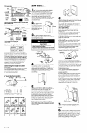
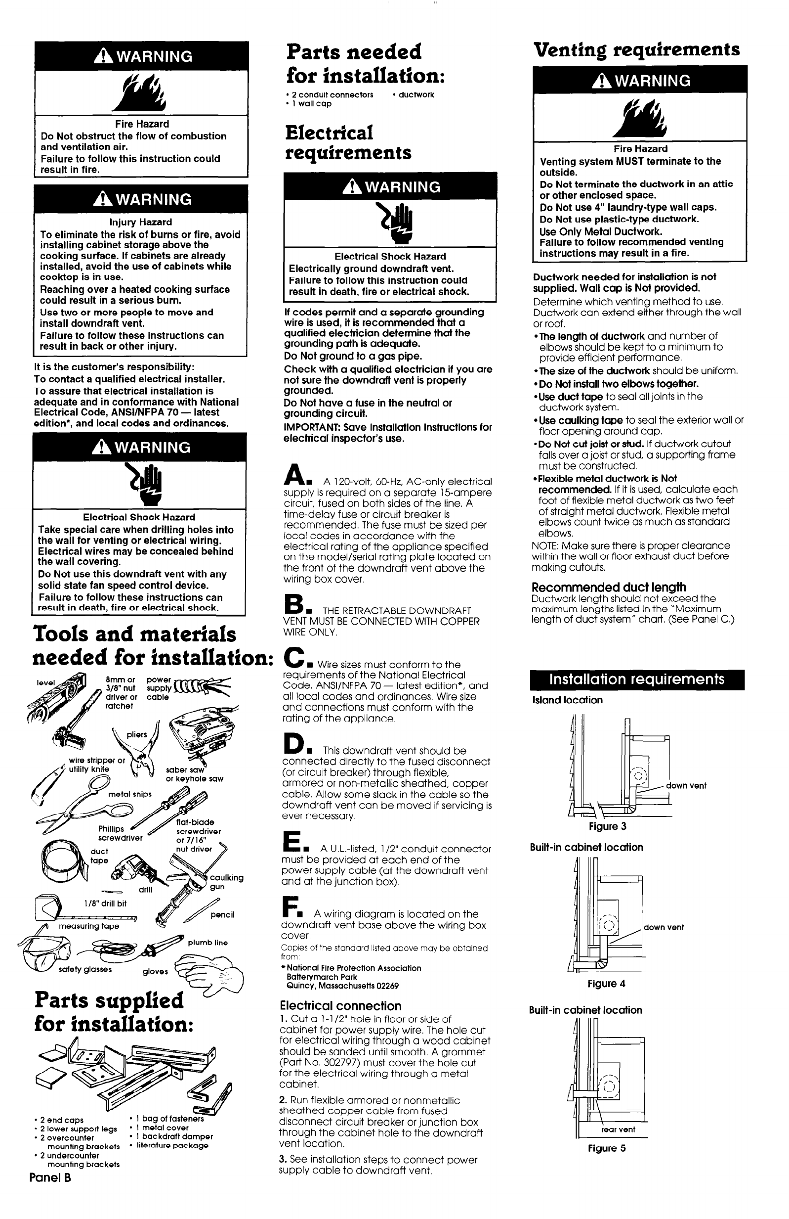
Figure 3
Built-in cabinet location
F
n
A wiring diagram is located on the
downdraft vent base above the wiring box
cover.
Copies of the standard listed above may be obtained
from.
*National Fire Protection Association
Batterymarch Park
Quincy, Massachusetts 02269
Figure 4
Electrical connection
Built-in cabinet location
1. Cut a l-l /2” hole in floor or side of
cabinet for power supply wire. The hole cut
for electrical wiring through a wood cabinet
should be sanded until smooth. A grommet
(Part No. 302797) must cover the hole cut
for the electrical wiring through a metal
cabinet.
2. Run flexible armored or nonmetallic
sheathed copper cable from fused
disconnect circuit breaker or junction box
through the cabinet hole to the downdraft
vent location.
Figure 5
3. See installation steps to connect power
supply cable to downdraft vent.
Venting requirements
Fire Hazard
Venting system MUST terminate to the
outside.
Do Not terminate the ductwork in an attic
or other enclosed space.
Do Not use 4” laundry-type wall caps.
Do Not use plastic-type ductwork.
Use Only Metal Ductwork.
Failure to follow recommended venting
instructions may result in a fire.
Ductwork needed for installation is not
supplied. Wall cap is Not provided.
Determine which venting method to use.
Ductwork can extend either through the wall
or roof.
*The length of ductwork and number of
elbows should be kept to a minimum to
provide efficient performance.
*The size of the ductwork should be uniform.
l
Do Not insfall two elbows together.
*Use duct tape to seal all joints in the
ductwork system.
l
Use caulking tape to seal the exterior wall or
floor opening around cap.
*Do Not cut joist or stud. If ductwork cutout
falls over a joist or stud, a supporting frame
must be constructed.
*Flexible metal ductwork is Not
recommended. If it is used, calculate each
foot of flexible metal ductwork as two feet
of straight metal ductwork. Flexible metal
elbows count twice as much as standard
elbows.
NOTE: Make sure there is proper clearance
within the wall or floor exhaust duct before
making cutouts,
Recommended duct length
Ductwork length should not exceed the
maximum lengths listed in the ‘Maximum
length of duct system” chart. (See Panel C.)
Island location
own vent