


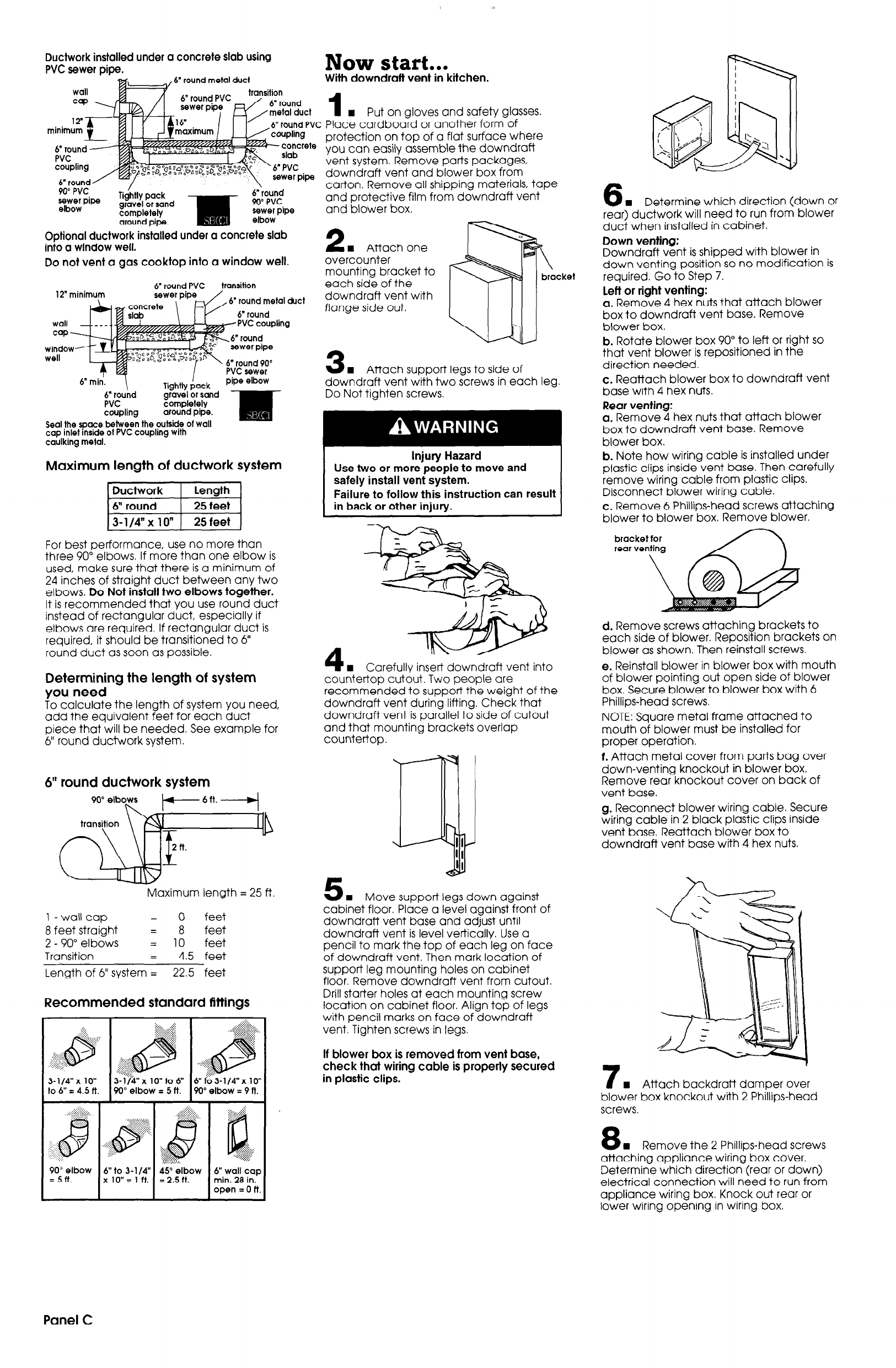
Ductwork installed under a concrete slab using
PVC sewer pipe.
Optional ductwork installed under a concrete slab
into a window well.
Do
not vent a
gas
cooktop into a window well,
12” minimum
6”
round PVC
concreie
slab
transition
6” round metal duct
6” round
T
6” min.
I
PVC sewer
Tiahtlv
oock
pipe elbow
6” rouhd
‘-G----I r --.-
PVC
gravel or sand
completely
coupling
around pipe.
Seal the space between the outside of wall
cap inlet inside of PVC coupling with
caulking metal.
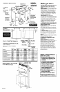
Maximum length of ductwork system
For best performance, use no more than
three 90” elbows. If more than one elbow is
used, make sure that there is a minimum of
24 inches of straight duct between any two
elbows. Do Not install two elbows together.
It is recommended that you use round duct
instead of rectangular duct, especially if
elbows are required. If rectangular duct is
required, it should be transitioned to 6”
round duct as soon as possible.
Determining the length of system
you need
To calculate the length of system you need,
add the equivalent feet for each duct
piece that will be needed. See example for
6” round ductwork system.
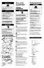
6” round ductwork system
6ft. -4
lb
Maximum length = 25 ft.
I-wallcap = 0
feet
8 feet straight
= 8 feet
2 - 90” elbows
= 10 feet
Transition
=
4.5 feet
Length of 6” system = 22.5 feet
Recommended standard fittings
:::::::; ..:::::
. . . . . -.- . . . . . -.
:i::
...-...-.-.-.-.-.-..i
. ..-.-.-.-..-... :
..i-I~~~ ~~~ ...~~~:-.
.::.:::.:>.:::; .-:..
3-l/&x 10” 3-l/$x lO”to6” 6”f;63-1/4”xlo”
to 6” = 4.5 ft.
90” elbow = 5 ft.
90” elbow = 9 ft.
PO; ;,lbow
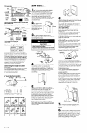
Now start...
With downdraft vent in kitchen.
1
n
Put on gloves and safety glasses.
Place cardboard or another form of
protection on top of a flat surface where
you can easily assemble the downdraft
vent system. Remove parts packages,
downdraft vent and blower box from
carton. Remove all shippina materials, tape
and protective film fro’& downdraft vent
and blower box.
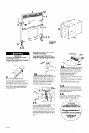
2
w Attach one
overcounter
mounting bracket to
each side of the
downdraft vent with
flange side out.
3
w Attach supper? legs to side of
downdraft vent with two screws in each leg.
Do Not tighten screws.
Injury Hazard
Use two or more people to move and
safely install vent system.
Failure to follow this instruction can result
in back or other injury.
4
w Carefullv insert downdraft vent into
countertop cut&t. Two people are
recommended to support the weight of the
downdraft vent during lifting. Check that
downdraft vent is parallel to side of cutout
and that mounting brackets overlap
countertop.
w Move support legs down against
cabinet floor. PI&e a le;el against-front of
downdraft vent base and adjust until
downdraft vent is level vertically. Use a
pencil to mark the top of each leg on face
of downdraft vent. Then mark location of
support leg mounting holes on cabinet
floor. Remove downdraft vent from cutout.
Drill starter holes at each mounting screw
location on cabinet floor. Align top of legs
with pencil marks on face of downdraft
vent. Tighten screws in legs.
If blower box is removed from vent base,
check that wiring cable is properly secured
in plastic clips.
6
H Determine which direction (down or
rear) ductwork will need to run from blower
duct when installed in cabinet.
Down venting:
Downdraft vent is shipped with blower in
down venting position so no modification is
required. Go to Step 7.
left or right venting:
a. Remove 4 hex nuts that attach blower
box to downdraft vent base. Remove
blower box.
b. Rotate blower box 90” to left or right so
that vent blower is repositioned in the
direction needed.
c. Reattach blower box to downdraft vent
base with 4 hex nuts.
Rear venting:
a. Remove 4 hex nuts that attach blower
box to downdraft vent base. Remove
blower box.
b. Note how wiring cable is installed under
plastic clips inside vent base. Then carefully
remove wiring cable from plastic clips.
Disconnect blower wiring cable.
c. Remove 6 Phillips-head screws attaching
blower to blower box. Remove blower.
bracket for
real venting
\
d. Remove screws attaching brackets to
each side of blower. Reposition brackets on
blower as shown. Then reinstall screws.
e. Reinstall blower in blower box with mouth
of blower pointing out open side of blower
box. Secure blower to blower box with 6
Phillips-head screws.
NOTE: Square metal frame attached to
mouth of blower must be installed for
proper operation.
f. Attach metal cover from parts bag over
down-venting knockout in blower box.
Remove rear knockout cover on back of
vent base.
g. Reconnect blower wiring cable. Secure
wiring cable in 2 black plastic clips inside
vent base. Reattach blower box to
downdraft vent base with 4 hex nuts.
7
w Attach backdraft damper over
blower box knockout with 2 Phillips-head
screws.
8
n
Remove the 2 Phillips-head screws
attaching appliance wirini box cover.
Determine which direction (rear or down)
electrical connection will need to run from
appliance wiring box. Knock out rear or
lower wiring opening in wiring box.
Panel
C