


INSTALLATION INSTRUCTIONS
Before you begin, read the following instructions
completely and carefully. If followed, they will
simplify the installation job.
IMPORTANT: OBSERVE ALL GOVERNING
CODES AND ORDINANCES
I
SAVE THESE INSTRUCTIONS FOR THE LOCAL
ELECTRICAL INSPECTOR’S USE.
I
STEP 1
ELECTRICAL REQUIREMENTS
This appliance may be connected by means of permanent “hard
wiring” or power supply cord kit.
It is the personal responsibility of the customer to contact a
qualified technician to assure that the electrical installation is
adequate and is in conformance with the National Electrical Code
ANSVNPFA 70- latest edition and local codes and ordinances.
THE RANGE MUST BE CONNECTED WITH COPPER WIRE
ONLY. Aluminum wire must not be used to avoid potentially
unsatisfactory connections.
POWER SUPPLY CORD KIT
This appliance must be connected with a power supply cord kit
rated at 125/250 volts minimum, 40 amperes, and marked for use
with ranges. Cord must have three (3) conductors.
For mobile home installation or in areas where local codes do not
permit grounding through neutral, a four (4) conductor power
supply cord kit rated at 125/250 volts minimum, 40 amperes, and
marked for use with ranges shall be used.
Terminals on end of wires must be either closed loop or open-end
spade lugs with upturned ends. Cord must have strain relief
clamp.
MODELS WITH FACTORY-CONNECTED POWER SUPPLY
CORD
Some models may be equipped with a factory-connected, three
(3) conductor, power supply cord.
In mobile home installations or in areas where local codes do not
permit grounding through neutral, a four (4) conductor power
supply cord kit rated at 125/250 volts minimum, 40 amperes and
investigated for use with ranges shall be used. Terminals on end
of wires must be either closed loop or open-end spade lugs with
upturned ends.
STEP 2
GENERAL
The back of a Free Standing Range may be Installed against
a vertical wall. The sides may be installed against base
cabinets or against vertical walls extending above the upper
edge of the cook top.
To prevent possible discoloration of the base cabinets,
the front of the oven frame must extend at least l/z” past the
front surface or cabinet doors of the base cabinets.
To eliminate the hazard of reaching over heated surface
elements, cabinets or storage spaces should not be provided
over a range.
If cabinets are provided, the hazard can be reduced by
installing a range hood that projects horizontally a
minlmum of 5 inches beyond the bottom of the cabinets.
CAUTION:
30 inches minimum clearance between the top
of the cooking surface and the bottom of an unprotected wood
or metal cabinet. 24 inches minimum when bottom of wood
or metal cabinet is protected by not less than %-inch-thick
flame-retardant millboard covered with not less than No. 28
MSG sheet steel, 0.015-inch-thick stamless steel, 0.024-inch-
thick aluminum, or 0.020-inch-thick copper.
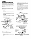
When installing the range between basecabinets, refer
to
Figure 1
for the size of the opening needed. Do Not
seal range to cabinets.
CAUTION:
When unpacking the range, do not discard the 4
shipping bolts as these are the leveling legs.
If a service cord is used, the wall receptacle should be
located in accordance with the dimensions given in
Figurel.
f
A-
15 S'R
TO
36 13 16
22 I,2"
Overall
"C" d
Heqht of
8'
I- '
Eye Level
Models IS
OI
1 MAX
663116
t
\
?
WALL
RECEPTACLE
“A” 30” RANGES - 30-3/E” TO 30~1/2”
40"
RANGES - 40-3/E” TO 40-l/2”
,, ,,
8
NOTE: COPPER SERVICE CORO OR
POWER SUPPLY CORD (PIGTAIL) MUST
RUN OOWNWARO, LEFT OR RIGHT TO
WALL RECEPTACLE TO AVOID PINCHING
CORD BETWEEN REAR PORTION OF
RANGE AND WALL.
“C” 30” & 40” RANGES - 15” TO 19”
MICROSHELF RANGE - 8” TO 10”
FIGURE 1
ON MODELSSO EQUIPPED: BESUAETHE BOlTLE
OF CLEANER -CONDITIONER, PACKED WITH THE
RANGE, IS LEFT WHERE THE USER CAN FIND IT
EASILY, IT IS IMPORTANT THAT THE GLASS-CE-
RAMIC SMOOTH TOP BE PRE-TREATED BEFORE
BEING USED.
2