EN8
FOR ELECTRICAL CONNECTION, SEE THE PARAGRAPH ON INSTALLATION
The induction oven is equipped with an electrical socket on the rear wall of the oven to supply power to
the heating element inside the induction plate when plugged in.
The induction plate is designed to work together with the induction cooking vessel supplied with the oven.
Improved cooking performances and energy consumption can be achieved by using the cooking vessel
and induction plate.
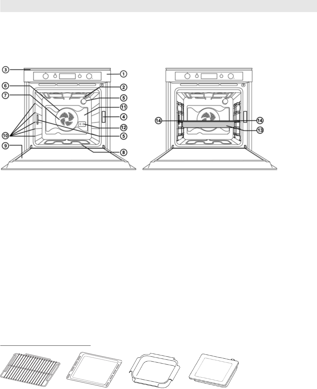
1. Control panel
2. Upper heating element/grill
3. Cooling fan (not visible)
4. Dataplate (not to be removed)
5. Lamps
6. Circular heating element (not visible)
7. Fan
8. Lower heating element (not visible)
9. Door
10. Position of shelves (the number of shelves is indicated on the front of the oven)
11. Rear wall
12. Electrical socket (inside oven)
13. Induction Plate
14. Induction Plate position
N.B.:
- During cooking, the cooling fan may switch on at intervals in order to minimise energy consumption.
- At the end of cooking, after the oven has been switched off, the cooling fan may continue to run for a
while.
- When the oven door is opened during cooking, the heating elements switch off.
ACCESSORIES SUPPLIED
A. WIRE SHELF (2): the wire shelf can be used to grill food or as a support for pans, cake tins and other
ovenproof cooking receptacles.
B. DRIP TRAY (1): the drip tray is designed to be positioned under the wire shelf in order to collect fat or
as an oven tray for cooking meat, fish, vegetables, focaccia, etc.
C. COOKING VESSEL (1): the cooking vessel is designed to be used with the induction plate and should
be placed according to the position markings on the induction plate glass.
D. INDUCTION PLATE (1): to be used in induction mode only by placing it on the third shelf position
and ensuring the electrical plug is fully inserted (refer to “Inserting wire shelves and other accessories
in the oven”).
INSTRUCTIONS FOR OVEN USE
Fig. A Fig. B Fig. C Fig. D


