


6
8.
If installing the range in a mobile
home, you must secure the range to the
floor. Any method of securing the range
is adequate as long as it conforms to the
“Manufactured Home Construction and
Safety Standard,” Page 2.
9.
Place rack in oven. Place level on
rack, first side to side; then front to back.
If range is not level, pull range forward
until rear leveling leg is removed from
the anti-tip bracket. Use 3/8" drive ratchet
and channel lock pliers to adjust leveling
legs up or down until range is level. Push
range back into position. Check that rear
leveling leg is engaged in anti-tip bracket.
NOTE: Oven must be level for satisfactory
baking conditions.
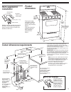
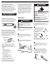
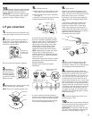
7.
Making sure the anti-tip bracket is
installed:
• Look for the anti-tip bracket securely
attached to floor.
• Slide range back so rear range foot is
under anti-tip bracket.
anti-tip
bracket
range foot
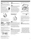
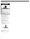
10.
Assemble the flexible connector
to the gas supply pipe to the pressure
regulator connection fitting, using the
adapter fittings provided with the flexible
connector. Use pipe-joint compound
made for use with L.P. gas to seal all pipe
thread connections.
regulator
connection
fitting
All connections must be wrench-tightened.
1/2" to 3/4"
gas pipe
nipple
manual
gas
shutoff
valve
black iron
pipe
union
pressure regulator
connection fitting
90˚elbow
Typical rigid
pipe connection
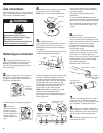
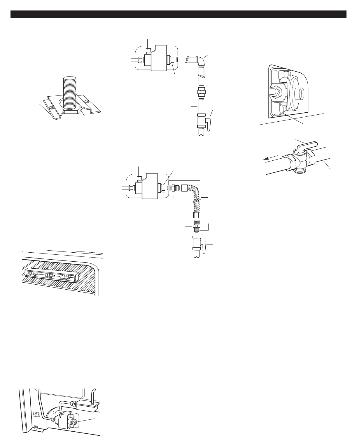
11.
If a flexible appliance connector
is used, be certain connector is not
kinked.
12.
Check that all control knobs are
in the “OFF” position.
adapter
adapter
manual
gas
shutoff
valve
A 1/2" male pipe thread is needed for connection to
pressure regulator female pipe threads.
1/2" to 3/4"
gas pipe
pressure regulator
connection fitting
Typical flexible connection
flexible
connector
use pipe-joint
compound
use pipe-joint
compound
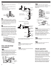
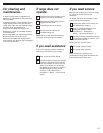
13.
Check that range regulator
shutoff valve is in the “on” position. Open
the manual shutoff valve in the gas
supply line.
manual shutoff valve
“open” position
gas supply
to range
regulator shutoff
valve in
“on” position
viewed from
inside broiler
compartment
Check operation
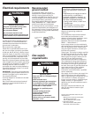
Gas and electrical
connection
Electronic ignition system.
Cooktop and oven burners use electronic
ignitors in place of standing pilots. When
a cooktop control knob is turned to the
“LITE” position, the system creates a
spark to light the burner. This sparking
continues until the control knob is turned
to the desired setting.
When the oven control is turned to the
desired setting, a hot surface ignitor
heats to a bright orange and ignites the
gas. No sparking occurs. The glow bar
remains on while the burner operates.
14.
Test all connections by brushing
on an approved non-corrosive leak-
detection solution. Bubbles will show a
leak. If a leak appears, shut off gas
supply valve and tighten connections.
Then check connections again. Clean all
leak-detection solution from gas
connections. Close broiler door.
15.
Place burners, burner caps and
grates on cooktop.
16.
Plug power supply cord into
grounded electrical outlet.