


9
L.P. gas conversion
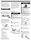
1.
Check that the manual shutoff valve
in the gas supply line has been turned off.
4.
Remove burner grates, burner caps,
burners and screws. Lift cooktop.
NOTE:There is no cooktop support rod.
5.
Cooktop burners:
a. Check that all control knobs are in the
OFF position and remove the knobs.
b. Remove the control panel. (See Step
17a, Page 7.)
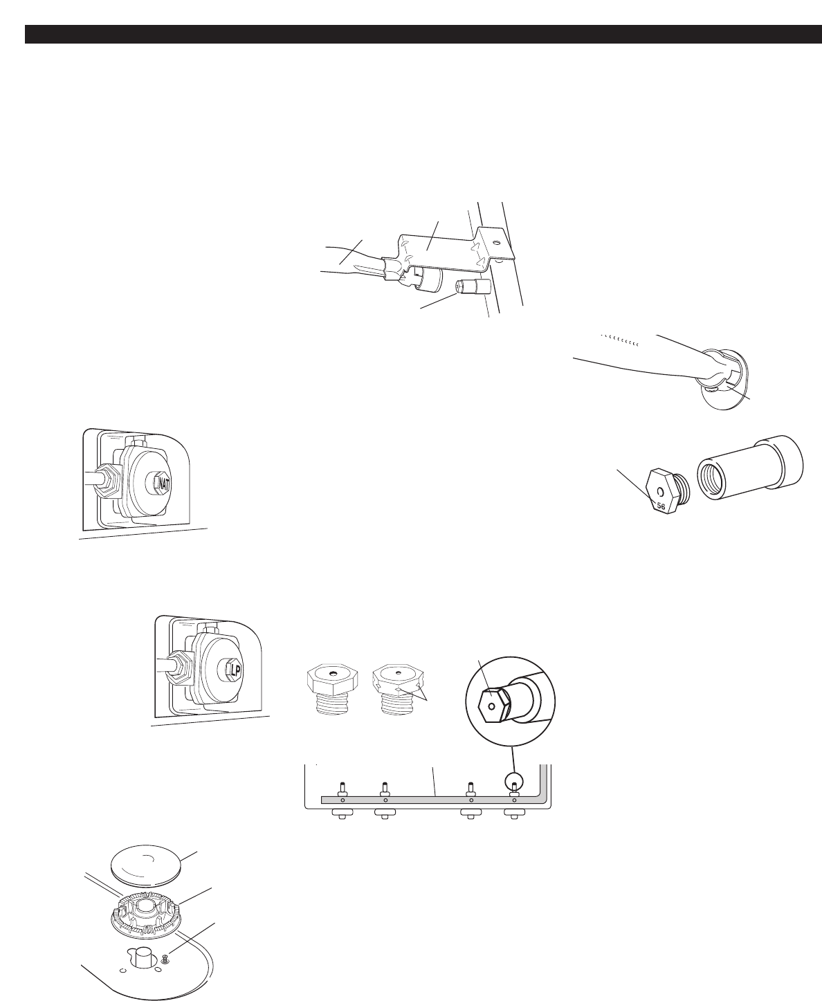
c. Lift front of bracket and push tube and
bracket assembly back off orifice.
6.
Oven burner:
a. Open oven door and remove oven
racks, oven tray, flame spreader and set
aside. Lift oven burner. The orifice spud is
behind the oven burner air shutter.
b. Locate L.P. gas orifice spud stamped
“56” in literature package supplied with
range.
c. Use a 3/8" combination wrench and
remove the natural gas orifice spud.
Install the number “56” L.P. gas spud.
Place natural gas oven burner spud in
plastic parts bag along with natural gas
cooktop burner spuds for future use and
keep with literature package.
d. Reinstall the oven burner.
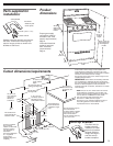
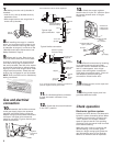
2.
Open broiler drawer and remove
broiler pan. The pressure regulator is
located in the back right hand corner of
the broiler compartment.
Do not remove the pressure regulator.
3.
Pressure
regulator: Remove
the cap from the
pressure regulator.
Turn the cap over
so that LP is visible.
Replace the cap.
burner
burner cap
screw
viewed from
inside broiler
compartment
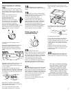
d. Locate L.P. gas orifice spuds for top
burners in literature package included
with the range. Three L.P. gas spuds are
stamped “65” and one “62”. Remove
Natural gas orifice spuds using a 3/8"
combination wrench. Install L.P. gas
orifice spuds in locations shown to
replace the Natural gas orifice spuds.
NOTE: Depending on model, the range
cooktop may be equipped with 4
standard burners or 3 standard burners
and 1 power burner. Spud size/location
remain the same.
Place Natural gas orifice spuds in plastic
parts bag for future use and keep with
literature package.
Reinstall burner tube and bracket
assemblies.
orifice spuds
NAT
L.P.
L.R.
L.F.
R.R.
R.F.
gas
manifold
notches
Remove and replace
orifice spuds.
NOTE: Burner tube and
brackets not shown.
“65”
“62”
“65”
“65”
oven burner
orifice behind
air shutter
L.P. oven orifice
spud stamped
with “56”
burner
tube
bracket
orifice
10.
Remove control knobs. Reinstall
the control panel. Securely tighten the 4
screws. Reinstall the control knobs.
IMPORTANT: If not done in Step 8, check
the “LO” flame adjustment. See “Check
operation” section, Step 19, Page 7.
e. Lower cooktop. Reinstall screws to
secure burner tubes to cooktop. Reinstall
burners, burner caps and burner grates.
Do not reinstall control panel or knobs.
They will be reinstalled in Step 10.
7.
Turn manual shutoff valve in gas
supply line on. If “Gas and electrical
connection” Steps 10–16 on Page 6 were
not completed, complete them now.
8.
Install control knobs. Check for
proper flame. The cooktop burner flames
should have a small inner cone with a
very distinct blue flame 1/4" (6.4 mm) to
1/2" (1.3 cm) long. The outer cone is not
as distinct as the inner cone. The oven
burner flame should be 1/2" (1.3 cm) long
with a bluish-green inner cone and dark
blue outer mantle. L.P. gas flames have a
slightly yellow tip. If the flames are noisy
or blowing, they are getting too much air.
If the flames are soft and lazy, they are
not getting enough air. If burners need
adjusting, see “Check operation” section,
Steps 17-22, Page 7.
9.
Close the broiler door. Turn oven
control knob to “OFF”.
10.
Remove control knobs. Reinstall
the control panel. Securely tighten the 4
screws. Reinstall the control knobs.
IMPORTANT: If not done in Step 8, check
the “LO” flame adjustment. See “Check
operation” section, Step 19, Page 7.