


Page 3-1
THE COOKTOP BURNER SYSTEM
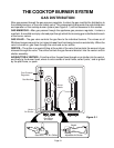
GAS DISTRIBUTION
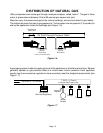
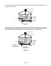
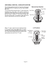
After gas passes through the gas pressure regulator, it enters the gas manifold for distribution to
the cooktop burners, or the oven safety valve. The components that provide the safe distribution
and operation of the cooktop burner system (see Figure 3-1) will be discussed in this section.
GAS MANIFOLD—After gas passes through the appliance gas pressure regulator, it enters a
manifold. A manifold is simply a formed pipe through which the incoming gas is distributed to each
of the burner valves.
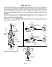
GAS VALVE—The gas valve controls the gas flow to the individual burners. The valves on all
Whirlpool ranges are push-to-turn types to keep them from being turned on accidentally. When the
valve is turned on, gas flows through the valve and out an orifice.
ORIFICE—The orifice is a special fitting at the outlet of the valve that controls the amount of gas
released through the valve. The orifice controls the gas flow and directs it into the venturi and air
shutter assembly.
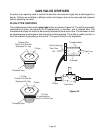
AIR SHUTTER & VENTURI—From the orifice, the gas flows through an air shutter into the venturi,
and finally to the burner head, where it exits a series of small holes, called “ports,” and is ignited
by the pilot flame, or spark.
Gas Pressure
Regulator
Gas Manifold
Burner
Heads
Gas Valves
& Orifices
Air Shutter
Venturi
Gas Valve
Orifice
Adjustable Air Shutter
Venturi
Figure 3-1