


Page 4-1
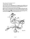
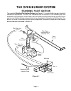
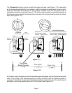
THE OVEN BURNER SYSTEM
STANDING PILOT IGNITION
OFF
N
A
T
L
P
Oven
Thermostat
Oven
Burner
Main Gas Line
Pilot Gas Line
Sensing Bulb &
Capillary Tube
Pilot
Assembly
Safety
Valve
Pilot Flame
Sensing Bulb &
Capillary Tube
Manifold
Gas In
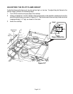
The complete
Standing Pilot Ignition System
(see Figure 4-1) is controlled by two very important
mechanical components. The first is a thermostat that is mounted on the manifold pipe and
accessible to the customer, and the other is an oven safety valve that controls the gas flow into the
oven burner. If either of these components is not working properly, the system will not function. The
burner, air shutter, and venturi are also critical components, and work the same as on the cooktop
burners that were discussed in Section 3.
Figure 4-1