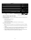
30
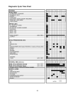
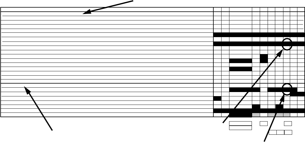
Using the Common Cycle Time Chart
To confirm the correct operation of a cycle or properly diagnosis a malfunction, the following informa-
tion must be determined:
• Does the model have a Soil Sensor?
• What cycle was chosen?
• What Cycle Option was chosen?
• What is the first fill water temperature? (Quick Clean / Time Saver Cycle only)
Proceed with the following steps:
1. Start the selected cycle and program the unit for Rapid Advance service feature. (See page
36).
2. Advance through the intervals to the one that will operate the load or perform the function to be
checked.
3. If the load does not operate, refer to the wiring diagram or applicable strip circuit to determine
what connections and components to check. (See Section Five - TECH TIPS.)
4. Whenever possible, check components for resistance or continuity. On components where
resistance or continuity checks are not reliable, conduct voltage checks.
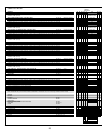
Wash Motor should be running
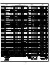
“CYCLE PROGRESSION & STATUS INDICATORS
PROG BAR W1
PROG BAR W2
WASHING (PROG BAR W3)
PROG BAR R1
CIRC (PROG BAR R2) (This LED will be labeled as ‘WASHING’ on models that use it, but it is on during all Wash and Rinse Periods)
RINSING
DRYING
SOAKING NOTE 7
SOAKING/SENSING NOTE 7
ADD-A-DISH
WATER HEATING (THERMAL HOLD INDICATOR) NOTE 6
SANITIZED NOTE 8,15
CLEAN NOTE 8
OUTPUT LOADS
WASH MOTOR (MAIN WINDING)
DRAIN MOTOR NOTE 2
FILL NOTE 2
APF ENABLED INTERVALS -Max # of APF Purges allowed in Interval NOTE 2
DETERGENT / RINSE AID DISPENSER
VENT
HEATER NOTES 4,10,11,16
17
16 15 14 13 12 11 10 9 8
3
15
94
11 11 11
Rinsing Indicator should be lIt
Fig. 4-4
(2)
(1)


