4-5
REMOVING THE ELECTRONIC CONTROL
HOUSING COMPONENTS
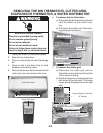
1. Unplug ice maker or disconnect power.
2. Open the ice maker door.
3. Cover or remove the ice from the storage
bin.
4. Remove the cutter grid cover and the cutter
grid (see page 4-2 for the procedures).
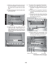
5. Disconnect the remaining two connectors
(bin and evaporator thermistors) from the
bottom of the control housing.
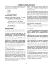
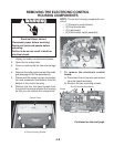
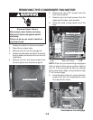
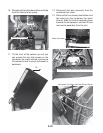
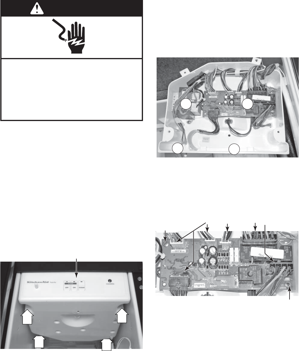
6. Remove the four hex-head screws from
the control housing and lower the housing
so that you can access the components.
4 Control Housing Screws
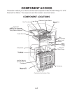
NOTE: The control housing components con-
sist of:
• (1) Electronic control board
• (2) Dual transformer
• (3) Light switch
• (4) Push-button switch assembly
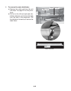
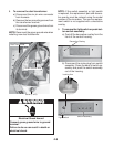
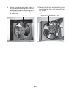
7. To remove the electronic control
board:
a) Disconnect the six harness connectors
from the board terminals.
b) Remove the two mounting screws.
Continued on the next page.
Control Panel
1
3
2
4
Six (6) Harness Connectors
Screw
Electronic Control Board
Screw
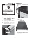
Electrical Shock Hazard
Disconnect power before servicing.
Replace all parts and panels before
operating.
Failure to do so can result in death or
electrical shock.
WARNING
WARNING


