


3
INSTALLATION REQUIREMENTS
Tools and Parts
Gather the required tools and parts before starting installation.
Read and follow the instructions provided with any tools listed
here.
Tools needed
Parts supplied
Check that all parts are included.
■ LP/Natural Gas Conversion Kit (located on back of range near
lower side)
■ Burner grates
■ Burner caps
■ Oven racks
■ 2 - #12 x 1⁵⁄₈" screws (for mounting anti-tip bracket)
■ Anti-tip bracket (taped inside upper oven with literature
package)
Anti-tip bracket must be securely mounted to the back wall or
floor. Thickness of flooring may require longer screws to
anchor bracket to subfloor. Longer screws are available from
your local hardware store.
Parts needed
Check local codes and consult gas supplier. Check existing gas
supply and electrical supply. See “Electrical Requirements” and
“Gas Supply Requirements” sections.
Location Requirements
IMPORTANT: Observe all governing codes and ordinances. Do
not obstruct flow of combustion and ventilation air.
■ It is the installer’s responsibility to comply with installation
clearances specified on the rating number plate. The rating
number plate is located behind the control panel.
■ The range should be located for convenient use in the
kitchen.
■ Recessed installations must provide complete enclosure of
the sides and rear of the range.
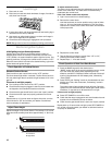
■ To eliminate the risk of burns or fire by reaching over heated
surface units, cabinet storage space located above the
surface units should be avoided. If cabinet storage is to be
provided, the risk can be reduced by installing a range hood
or microwave hood combination that projects horizontally a
minimum of 5" (12.7 cm) beyond the bottom of the cabinets.
■ All openings in the wall or floor where range is to be installed
must be sealed.
In the State of Massachusetts, the following installation instructions apply:
■ Installations and repairs must be performed by a qualified or licensed contractor, plumber, or gasfitter qualified or licensed by
the State of Massachusetts.
■ If using a ball valve, it shall be a T-handle type.
■ A flexible gas connector, when used, must not exceed 3 feet.
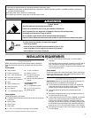
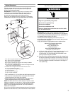
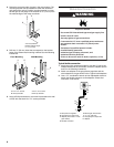
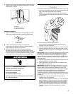
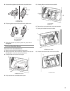
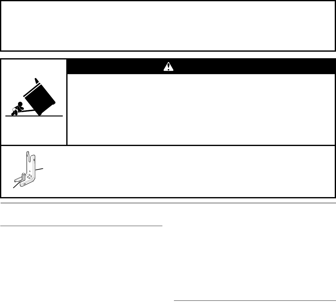
Tip Over Hazard
A child or adult can tip the range and be killed.
Install anti-tip bracket to floor or wall per installation instructions.
Slide range back so rear range foot is engaged in the slot of the anti-tip bracket.
Re-engage anti-tip bracket if range is moved.
Do not operate range without anti-tip bracket installed and engaged.
Failure to follow these instructions can result in death or serious burns to children and adults.
To verify the anti-tip bracket is installed and engaged:
• Slide range forward.
• Look for the anti-tip bracket securely attached to floor or wall.
• Slide range back so rear range foot is under anti-tip bracket.
• See installation instructions for details.
WARNING
Anti-Tip
Bracket
Range Foot
■ Tape measure
■ Phillips screwdriver
■ Tor x
®†
T-20
®
screwdriver
■ Flat-blade screwdriver
■ ¹⁄₈" flat-blade screwdriver
■ Level
■ Hand or electric drill
■ Wrench or pliers
■ Pipe wrench
■ ¹⁵⁄₁₆" combination wrench
■ ¹⁄₈" (3.2 mm) drill bit
■ Marker or pencil
■ Pipe-joint compound
resistant to LP gas
■ Noncorrosive leak-detection
solution
For LP/Natural Gas
Conversions
■ ½" combination wrench
■ ⁹⁄₃₂" (7.0 mm) nut driver
■ Masking tape
†®TORX and T-20 are registered trademarks of Saturn Fasteners, Inc.