


8
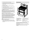
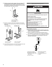
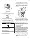
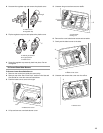
3. Determine and mark edge of range in the cutout space. The
mounting bracket can be installed on either the left side or
right side of the cutout. Position mounting bracket in cutout
so that right (or left) edge of the bracket is ¹⁵⁄₁₆" (2.4 cm) from
the marked edge of the range, as shown.
4. Drill two ¹⁄₈" (3.0 mm) holes that correspond to the bracket
holes of the determined mounting method. See the following
illustrations.
5. Using a Phillips screwdriver, mount anti-tip bracket to the wall
or floor with the two #12 x 1⁵⁄₈" screws provided.
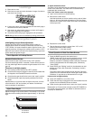
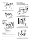
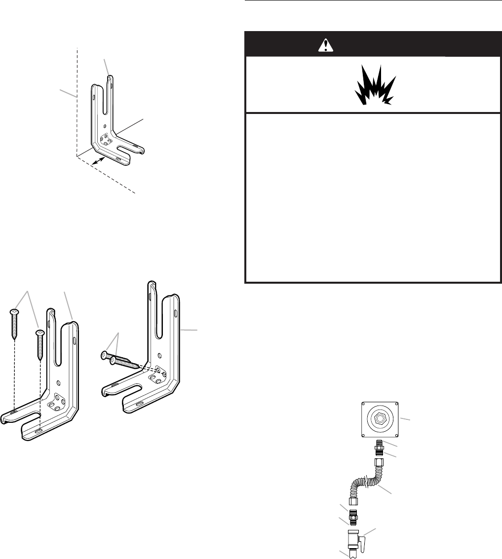
Make Gas Connection
Typical flexible connection
1. Apply pipe-joint compound made for use with LP gas to the
smaller thread ends of the flexible connector adapters (see B
and G in the following illustration).
2. Attach one adapter to the gas pressure regulator and the
other adapter to the gas shutoff valve. Tighten both adapters.
3. Use a ¹⁵⁄₁₆" combination wrench and an adjustable wrench to
attach the flexible connector to the adapters. Check that
connector is not kinked.
A.Anti-tip bracket
B.Mark edge of range.
C.¹⁵⁄₁₆" (2.4 cm)
Floor Mounting Wall Mounting
A.#12 x 1⁵⁄₈" screws
B.Anti-tip bracket
A.#12 x 1⁵⁄₈" screws
B.Anti-tip bracket
A
B
C
A
B
A
B
A.Gas pressure regulator
B.Use pipe-joint compound.
C.Adapter (must have ½" male
pipe thread)
D.Flexible connector
E.Manual gas shutoff valve
F. ½" or ¾" gas pipe
G.Use pipe-joint compound.
H.Adapter
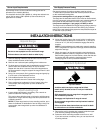
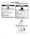
WARNING
Explosion Hazard
Use a new CSA International approved gas supply line.
Install a shut-off valve.
Securely tighten all gas connections.
If connected to LP, have a qualified person make sure
gas pressure does not exceed 14" (36 cm) water
column.
Examples of a qualified person include:
licensed heating personnel,
authorized gas company personnel, and
authorized service personnel.
Failure to do so can result in death, explosion, or fire.
A
B
C
D
E
F
G
H